
Page 343 - Power Electronics Handbook
P. 343
Output voltage control 333
Tnbk 13.23 € I d content dn sine modal.ted M-dircrtiolul wave with fTlfs = u)
Harmonic R. M.S. voltage as percentage of d.c. supply
number
0.1 0.2 0.3 0.4 0.5 0.6 0.7 0.8 0.9 0.98
1 7.23 13.9 21.1 28.1 35.0 42.1 49.9 56.5 63.9 70.7
2 0.01 0.02 0.02 0.10 0.34 0.07 0.79 0.11 0.03 0.27
3 0.05 0.56 0.24 0.19 0.35 0.16 0.14 0.10 0.49 0.22
4 0.01 0 0.06 0.71 0.43 0.03 0.02 0.18 0.86 0.03
5 0.50 0.13 0.05 0.42 0.12 0.13 0.43 0.61 0.75 0.14
6 0 0.04 0.01 0.37 0.11 0.01 0.35 0.28 0.76 0.62
7 0.63 1.02 0.32 0.29 0.80 0.40 0.17 0.17 0.78 0.62
8 0.02 0 0.02 0.76 0.28 0.22 0.70 0.54 0.25 0.01
9 1.03 0.98 0.63 0.86 0.19 0.03 0.19 0.03 0.32 0.22
10 0.02 0.09 0.04 0.31 0.42 0.10 0.12 0.06 0.37 0.22
11 0.35 0.18 0.25 0.13 0.48 0.36 0.12 0.12 0.03 0.14
12 0.03 0.18 0.14 0.07 0.35 0.11 0.11 0.45 0.10 0.10
13 0.22 0.03 0.15 1.05 0.13 0.78 0.14 0.65 0.73 0.33
14 0.06 0.14 0.06 0.05 0.14 0.17 0.34 0.66 0.50 0.30
15 0.13 0.76 0.29 1.14 0.28 0.75 0.07 0.48 0.70 0.56
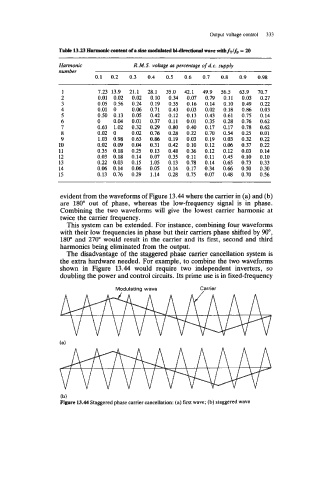
evident from the waveforms of Figure 13.44 where the carrier in (a) and (b)
are 180" out of phase, whereas the low-frequency signal is in phase.
Combining the two waveforms will give the lowest carrier harmonic at
twice the carrier frequency.
This system can be extended. For instance, combining four waveforms
with their low frequencies in phase but their carriers phase shifted by No,
180" and 270" would result in the carrier and its first, second and third
harmonics being eliminated from the output.
The disadvantage of the staggered phase carrier cancellation system is
the extra hardware needed. For example, to combine the two waveforms
shown in Figure 13.44 would require two independent inverters, so
doubling the power and control circuits. Its prime use is in fixed-frequency
Modulating wave Carrier
V V V V V V V V V I
(b)
Figure 13.44 Staggered phase carrier cancellation: (a) first wave; (b) staggered wave