
Page 84 - Power Electronics Handbook
P. 84
Trigger devices 77
Base 1 gold wire
silicon
Ea& 2 ohmic
‘b) contact
Aluminium
(,.) Base 2 contact
/ I I I I I
Cut-off <Negative,/y ‘E 4
f
region 1 resistance p Saturation
(e) region region
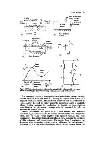
pb.rc 3.3 Unijuncthn transistor: (a) aeries bar acucmbly; (b) cube assembly; (c) planar
diffwcd assembly; (d) symbol and biasing; (e) cbarecteristic; (0 dotor circuit
The increasing current is accompanied by a reduction of voltage, causing
further emission from the emitter, resulting in regenerative action or a
negative resistance effect. This is shown clearly in the characteristics of
Figure 3.3(e). Beyond the valley point the saturation region is reached,
where further increase in conduction is limited by hole-electron
recombination, so the emitter voltage must be increased in order to
increase the emitter current.
Several parameters are given in UJT data sheets. The interbase
resistance ?BB is mehureci bcm een the two base terminals with the emitter
open, and its value varies slightly with applied voltage and with
temperature, data sheets normally providing a curve showing the variation
of this resistance with temperature. The emitter-base 1 resistance re]
decreases with increasing emitter current, although the emitter-base 2
resistance is not significantly affected by this current change. When the