
Page 180 - Power Quality in Electrical Systems
P. 180
162 Chapter Eleven
N 6-jack
L
G
Server
Distur. N-G sw
signal
Clients
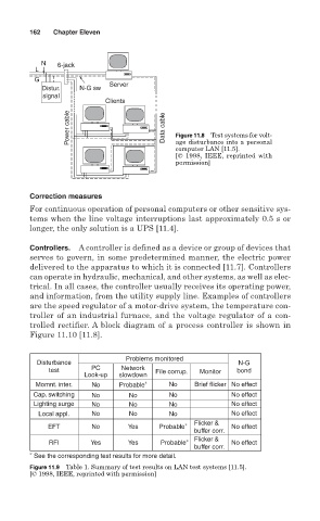
Power cable Data cable Figure 11.8 Test systems for volt-
age disturbance into a personal
computer LAN [11.5].
[© 1998, IEEE, reprinted with
permission]
Correction measures
For continuous operation of personal computers or other sensitive sys-
tems when the line voltage interruptions last approximately 0.5 s or
longer, the only solution is a UPS [11.4].
Controllers. A controller is defined as a device or group of devices that
serves to govern, in some predetermined manner, the electric power
delivered to the apparatus to which it is connected [11.7]. Controllers
can operate in hydraulic, mechanical, and other systems, as well as elec-
trical. In all cases, the controller usually receives its operating power,
and information, from the utility supply line. Examples of controllers
are the speed regulator of a motor-drive system, the temperature con-
troller of an industrial furnace, and the voltage regulator of a con-
trolled rectifier. A block diagram of a process controller is shown in
Figure 11.10 [11.8].
Problems monitored
Disturbance N-G
test PC Network File corrup. Monitor bond
Look-up slowdown
Momnt. inter. No Probable ∗ No Brief flicker No effect
Cap. switching No No No No effect
Lighting surge No No No No effect
Local appl. No No No No effect
EFT No Yes Probable ∗ Flicker & No effect
buffer corr.
∗ Flicker &
RFI Yes Yes Probable No effect
buffer corr.
∗ See the corresponding test results for more detail.
Figure 11.9 Table 1. Summary of test results on LAN test systems [11.5].
[© 1998, IEEE, reprinted with permission]