
Page 185 - Power Quality in Electrical Systems
P. 185
Power Quality Events 167
Force = (Bm sin wt ) 2
Bm 2 K
K
A A
Avg. Force = 1 ( Bm 2 )
Bm 2 K
p p 3p 2p
/ 2 / 2 wt
Flux density = Bm sin wt
1 cycle supply
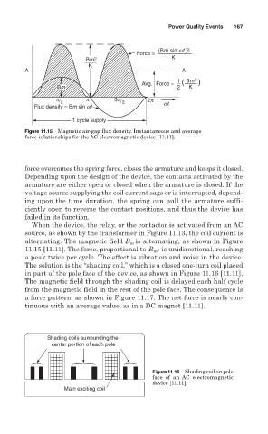
Figure 11.15 Magnetic air-gap flux density. Instantaneous and average
force relationships for the AC electromagnetic device [11.11].
force overcomes the spring force, closes the armature and keeps it closed.
Depending upon the design of the device, the contacts activated by the
armature are either open or closed when the armature is closed. If the
voltage source supplying the coil current sags or is interrupted, depend-
ing upon the time duration, the spring can pull the armature suffi-
ciently open to reverse the contact positions, and thus the device has
failed in its function.
When the device, the relay, or the contactor is activated from an AC
source, as shown by the transformer in Figure 11.13, the coil current is
alternating. The magnetic field B is alternating, as shown in Figure
m
11.15 [11.11]. The force, proportional to B m 2 is unidirectional, reaching
a peak twice per cycle. The effect is vibration and noise in the device.
The solution is the “shading coil,” which is a closed one-turn coil placed
in part of the pole face of the device, as shown in Figure 11.16 [11.11].
The magnetic field through the shading coil is delayed each half cycle
from the magnetic field in the rest of the pole face. The consequence is
a force pattern, as shown in Figure 11.17. The net force is nearly con-
tinuous with an average value, as in a DC magnet [11.11].
Shading coils surrounding the
center portion of each pole
Figure 11.16 Shading coil on pole
face of an AC electromagnetic
device [11.11].
Main exciting coil