
Page 181 - Power Quality in Electrical Systems
P. 181
Power Quality Events 163
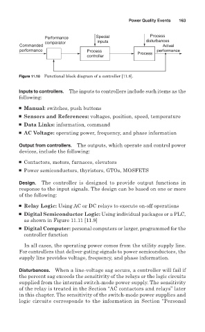
Performance Special Process
comparator inputs disturbances
Commanded Actual
performance Process performance
controller Process
Figure 11.10 Functional block diagram of a controller [11.8].
Inputs to controllers. The inputs to controllers include such items as the
following:
■ Manual: switches, push buttons
■ Sensors and References: voltages, position, speed, temperature
■ Data Links: information, command
■ AC Voltage: operating power, frequency, and phase information
Output from controllers. The outputs, which operate and control power
devices, include the following:
■ Contactors, motors, furnaces, elevators
■ Power semiconductors, thyristors, GTOs, MOSFETS
Design. The controller is designed to provide output functions in
response to the input signals. The design can be based on one or more
of the following:
■ Relay Logic: Using AC or DC relays to execute on-off operations
■ Digital Semiconductor Logic: Using individual packages or a PLC,
as shown in Figure 11.11 [11.9]
■ Digital Computer: personal computers or larger, programmed for the
controller function
In all cases, the operating power comes from the utility supply line.
For controllers that deliver gating signals to power semiconductors, the
supply line provides voltage, frequency, and phase information.
Disturbances. When a line-voltage sag occurs, a controller will fail if
the percent sag exceeds the sensitivity of the relays or the logic circuits
supplied from the internal switch-mode power supply. The sensitivity
of the relay is treated in the Section “AC contactors and relays” later
in this chapter. The sensitivity of the switch-mode power supplies and
logic circuits corresponds to the information in Section “Personal