Page 182 - Power Quality in Electrical Systems
P. 182

164   Chapter Eleven


                                Vsd
        Vcf                                          Sin
          Phase A      Phase voltage
               ABC                   Phase rotation  PLL
                        estimation
        Vcf Phase B             Vsq  identification  (Fig. 4)  Cos
                  DQ
                                Icfd
                       Phase capacitor
                        estimation
        IL  Phase A             Icfq
        IL Phase B  ABC         Isd   Harmonic controllers
                       Phase current  Isq  3rd, 5th, 7th, 9th, 11th, 13th
        IL Phase C  DQ  estimation        (Fig. 3)
                             –                                          Q1
                                                   Pos +  −
         Vdc  +              +  Esd                seq
                                                   sq
                P1 REG                  Pos D                 Kc        Q2
                                      p         pe
                                   DQ   P1 REG  DQ   +    +
           –                                                            Q3
                             –
         Ref                                                        Space vector modulation
                                                    Pos +  –            Q4
                                        Pos Q
                                                 p
                                                    sq
                             +  Esq    pe  P1 REG  DQ  seq    Kc
                                    DQ
                                                      +    +            Q5
                                      n  Neg D    ne                    Q6
                                   DQ   P1 REG  DQ
                                                              Limitation
                                      ne  Neg Q    n      Reset
                                    DQ  P1 REG  DQ
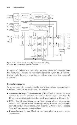
        Figure 11.11 Controller utilizing digital components [11.9].
        [© 2005, IEEE, reprinted with permission]
        Computers”. Where the controller requires phase information from
        the supply line, such as for base drive signals in Figure 11.12, the con-
        troller might be more sensitive to voltage sags than the personal
        computer.

        Correction measures
        To keep a controller operating in the face of line-voltage sags and inter-
        ruptions, the following equipment can be used:
        ■ Constant-Voltage Transformers (CVs): Used to correct for sags
          down to 30 percent of rated line voltage for one cycle, and down to
          70 percent continuously for a full load, as described in Chapter 8.
        ■ UPSs: For all conditions except line-voltage phase information.
          Assume that the controlled load is operating from the supply line to
          the UPS so that phase information from the UPS is of no use during
          deep and long sags or interruptions.
        ■ Phase-Locked Loop: Used in the controller to provide phase
          information.
   177   178   179   180   181   182   183   184   185   186   187