
Page 184 - Power Quality in Electrical Systems
P. 184
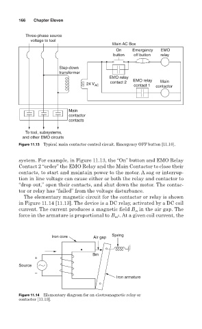
166   Chapter Eleven


           Three-phase source
             voltage to tool
                                             Main AC Box
                                               On    Emergency  EMO
                                              button  off button   relay

                        Step-down
                        transformer
                                            EMO relay  EMO relay
                                                                Main
                                   24 V AC  contact 2   contact 1   contactor


                            Main
                            contactor
                            contacts
           To tool, subsystems,
          and other EMO circuits
        Figure 11.13 Typical main contactor control circuit. Emergency OFF button [11.10].


        system. For example, in Figure 11.13, the “On” button and EMO Relay
        Contact 2 “order” the EMO Relay and the Main Contactor to close their
        contacts, to start and maintain power to the motor. A sag or interrup-
        tion in line voltage can cause either or both the relay and contactor to
        “drop out,” open their contacts, and shut down the motor. The contac-
        tor or relay has “failed” from the voltage disturbance.
          The elementary magnetic circuit for the contactor or relay is shown
        in Figure 11.14 [11.13]. The device is a DC relay, activated by a DC coil
        current. The current produces a magnetic field B in the air gap. The
                                                      m
        force in the armature is proportional to B m 2 . At a given coil current, the


                     Iron core        Air gap  Spring


                                     Bm
               +
        Source
               –
                                               Iron armature


        Figure 11.14 Elementary diagram for an electromagnetic relay or
        contactor [11.13].