
Page 183 - Power Quality in Electrical Systems
P. 183
Power Quality Events 165
Q1 Q3 Q5
Lf L C
Load
Lf L
Lf L
Q2 Q4 Q6
V1 V2 V3
cf cf cf
Phase A current Phase B current Phase C current Dual IGBT Dual IGBT Dual IGBT
drive
drive
drive
ADMC 401 DSP controller board V DC
Vcf Phase B
Vcf Phase A
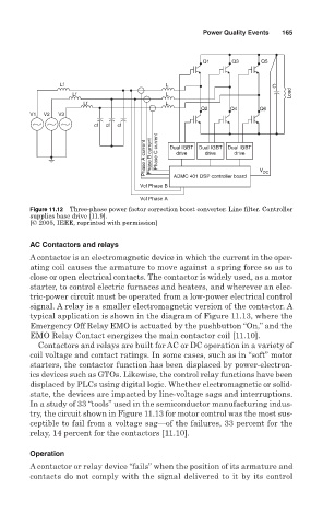
Figure 11.12 Three-phase power factor correction boost converter. Line filter. Controller
supplies base drive [11.9].
[© 2005, IEEE, reprinted with permission]
AC Contactors and relays
A contactor is an electromagnetic device in which the current in the oper-
ating coil causes the armature to move against a spring force so as to
close or open electrical contacts. The contactor is widely used, as a motor
starter, to control electric furnaces and heaters, and wherever an elec-
tric-power circuit must be operated from a low-power electrical control
signal. A relay is a smaller electromagnetic version of the contactor. A
typical application is shown in the diagram of Figure 11.13, where the
Emergency Off Relay EMO is actuated by the pushbutton “On,” and the
EMO Relay Contact energizes the main contactor coil [11.10].
Contactors and relays are built for AC or DC operation in a variety of
coil voltage and contact ratings. In some cases, such as in “soft” motor
starters, the contactor function has been displaced by power-electron-
ics devices such as GTOs. Likewise, the control relay functions have been
displaced by PLCs using digital logic. Whether electromagnetic or solid-
state, the devices are impacted by line-voltage sags and interruptions.
In a study of 33 “tools” used in the semiconductor manufacturing indus-
try, the circuit shown in Figure 11.13 for motor control was the most sus-
ceptible to fail from a voltage sag—of the failures, 33 percent for the
relay, 14 percent for the contactors [11.10].
Operation
A contactor or relay device “fails” when the position of its armature and
contacts do not comply with the signal delivered to it by its control