
Page 33 - Power Quality in Electrical Systems
P. 33
16 Chapter Two
Harmonic
AC source
source Customer #1
R s jX s V PCC
LOAD
I h
Customer #2
LOAD
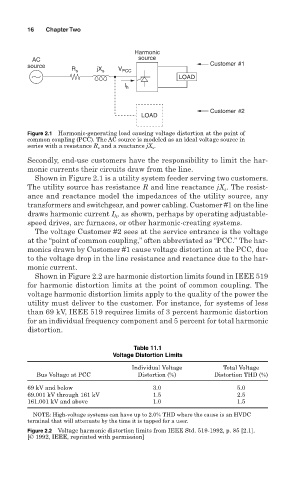
Figure 2.1 Harmonic-generating load causing voltage distortion at the point of
common coupling (PCC). The AC source is modeled as an ideal voltage source in
series with a resistance R s and a reactance jX s .
Secondly, end-use customers have the responsibility to limit the har-
monic currents their circuits draw from the line.
Shown in Figure 2.1 is a utility system feeder serving two customers.
The utility source has resistance R and line reactance jX . The resist-
s
ance and reactance model the impedances of the utility source, any
transformers and switchgear, and power cabling. Customer #1 on the line
draws harmonic current I , as shown, perhaps by operating adjustable-
h
speed drives, arc furnaces, or other harmonic-creating systems.
The voltage Customer #2 sees at the service entrance is the voltage
at the “point of common coupling,” often abbreviated as “PCC.” The har-
monics drawn by Customer #1 cause voltage distortion at the PCC, due
to the voltage drop in the line resistance and reactance due to the har-
monic current.
Shown in Figure 2.2 are harmonic distortion limits found in IEEE 519
for harmonic distortion limits at the point of common coupling. The
voltage harmonic distortion limits apply to the quality of the power the
utility must deliver to the customer. For instance, for systems of less
than 69 kV, IEEE 519 requires limits of 3 percent harmonic distortion
for an individual frequency component and 5 percent for total harmonic
distortion.
Table 11.1
Voltage Distortion Limits
Individual Voltage Total Voltage
Bus Voltage at PCC Distortion (%) Distortion THD (%)
69 kV and below 3.0 5.0
69.001 kV through 161 kV 1.5 2.5
161.001 kV and above 1.0 1.5
NOTE: High-voltage systems can have up to 2.0% THD where the cause is an HVDC
terminal that will attenuate by the time it is tapped for a user.
Figure 2.2 Voltage harmonic distortion limits from IEEE Std. 519-1992, p. 85 [2.1].
[© 1992, IEEE, reprinted with permission]