
Page 34 - Power Quality in Electrical Systems
P. 34
Power-Quality Standards 17
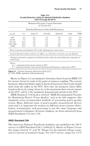
Table 10.3
Current Distortion Limits for General Distribution Systems
(120 V Through 69 000 V)
Maximum Harmonic Current Distortion
in Percent of I L
Individual Harmonic Order (Odd Harmonics)
<11 11≤h<17 17≤h<23 23≤h<35 35≤h TDD
I SC /I L
<20* 4.0 2.0 1.5 0.6 0.3 5.0
20<50 7.0 3.5 2.5 1.0 0.5 8.0
50<100 10.0 4.5 4.0 1.5 0.7 12.0
100<1000 12.0 5.5 5.0 2.0 1.0 15.0
>1000 15.0 7.0 6.0 2.5 1.4 20.0
Even harmonics are limited to 25% of the odd harmonic limits above.
Current distortions that result in a dc offset, e.g., half-wave converters, are not allowed.
*All power generation equipment is limited to these values of current distortion, regardless of
actual I SC /I L .
Where
I SC maximum short-circuit current at PCC.
I L maximum demand load-current (fundamental frequency component) at PCC.
Figure 2.3 Current harmonic distortion limits [2.1].
[© 1992, IEEE, reprinted with permission]
Shown in Figure 2.3 are harmonic distortion limits found in IEEE 519
for current drawn by loads at the point of common coupling. The current
harmonic distortion limits apply to limits of harmonics that loads should
draw from the utility at the PCC. Note that the harmonic limits differ
based on the I /I rating, where I SC is the maximum short-circuit current
SC L
at the PCC, and I is the maximum demand load current at the PCC.
L
IEEE Standard 1159 [2.2] is entitled “IEEE Recommended Practice
for Monitoring Electric Power Quality,” and as its title suggests, this
standard covers recommended methods of measuring power-quality
events. Many different types of power-quality measurement devices
exist and it is important for workers in different areas of power distri-
bution, transmission, and processing to use the same language and
measurement techniques. In future chapters, we draw extensively from
IEEE Standards 519 and 1159.
ANSI Standard C84
The American National Standards Institute sets guidelines for 120-V
service in ANSI Standard C84-1 (1999) [2.3]. Shown in Figure 2.4 are
the ranges labeled “A” and “B.” Range A is the optimal voltage range,
and is 5 percent of nominal voltage. For 120-V service, range A is 114 V