
Page 114 - Practical Control Engineering a Guide for Engineers, Managers, and Practitioners
P. 114
A New Domain and More Process Models 89
I_:r ~~t:·?\7 \:71
1
o 10 20 30 40 50 60 70 80 90 100
1r---r---~~,---~----~~--~--~~-,.-~
>-- 0
10 20 30 40 50 60 70 80 90 100
i_:r~r~7~7J
1
o 10 20 30 40 50 60 70 80 90 100
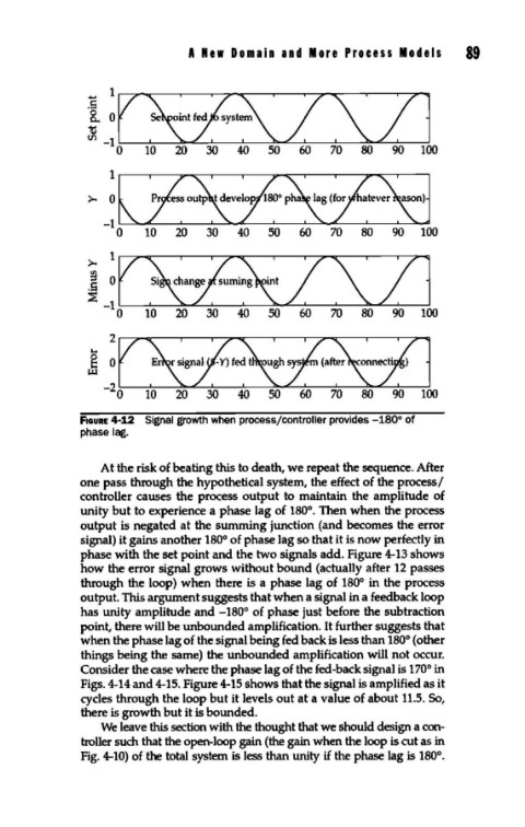
FIGURE 4-12 Signal growth when process/controller provides -180° of
phase lag.
At the risk of beating this to death, we repeat the sequence. After
one pass through the hypothetical system, the effect of the process I
controller causes the process output to maintain the amplitude of
unity but to experience a phase lag of 180°. Then when the process
output is negated at the summing junction (and becomes the error
signal) it gains another 180° of phase lag so that it is now perfectly in
phase with the set point and the two signals add. Figure 4-13 shows
how the error signal grows without bound (actually after 12 passes
through the loop) when there is a phase lag of 180° in the process
output. This argument suggests that when a signal in a feedback loop
has unity amplitude and -180° of phase just before the subtraction
point, there will be unbounded amplification. It further suggests that
when the phase lag of the signal being fed back is less than 180° (other
things being the same) the unbounded amplification will not occur.
Consider the case where the phase lag of the fed-back signal is 170° in
Figs. 4-14 and 4-15. Figure 4-15 shows that the signal is amplified as it
cycles through the loop but it levels out at a value of about 11.5. So,
there is growth but it is bounded.
We leave this section with the thought that we should design a con-
troller such that the open-loop gain (the gain when the loop is cut as in
Fig. 4-10) of the total system is less than unity if the phase lag is 180°.