
Page 165 - Practical Control Engineering a Guide for Engineers, Managers, and Practitioners
P. 165
140 C h a p t e r F iY e
where the dependence on the critical radian frequency m, is shown.
(Note that Eq. (5-17) is a consequence of the expression el = -1 that
11
we mentioned in App. B). Actually, Eq. (5-17) depends on both m, and
the critical control gain k, (if the control is proportional-only). If the
control is integral-only then the critical control gain would be 1,. Since
Eq. (5-17) is now a complex equation, there are real and imaginary
parts. Therefore, there are two equations in the two unknowns,
m, and k,. This argument suggests that the pole-finding approach
and the Bode plot approach are basically the same.
5-5 Multitank Processes
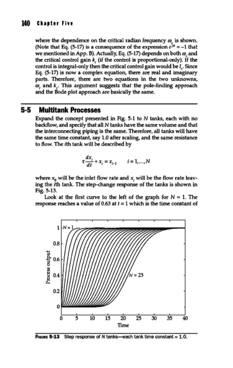
Expand the concept presented in Fig. 5-1 toN tanks, each with no
backflow, and specify that all N tanks have the same volume and that
the interconnecting piping is the same. Therefore, all tanks will have
the same time constant, say 1.0 after scaling, and the same resistance
to flow. The ith tank will be described by
dx.
r-' +x. =x. i = 1, ... ,N
dt I 1- 1
where x will be the inlet flow rate and X; will be the flow rate leav-
0
ing the ith tank. The step-change response of the tanks is shown in
Fig. 5-13.
Look at the first curve to the left of the graph for N = 1. The
response reaches a value of 0.63 at t = 1 which is the time constant of
1
0.8
"5
~0.6
0
~
~ 0.4
p..
0.2
0 5 10 15 20 25 30 35 40
Ttme
F1auRE 5-13 Step response of N tanks-each tank time constant = 1.0.