
Page 220 - Practical Control Engineering a Guide for Engineers, Managers, and Practitioners
P. 220
194 Chapter Seven
1.4 r-.........,..-~-~---"'T"----r--~~---;:=t::=:.====;J
-Steam T
.. OutletT
1.2
- Setpoint
1~-----.~ .. ~.----------------------------~
0.8
0.6 P = 1 I= 10 D = 0
0.4
0.2 ~
0
0 0.2 0.4 0.6 0.8 1 1.2 1.4 1.6 1.8 2
Time
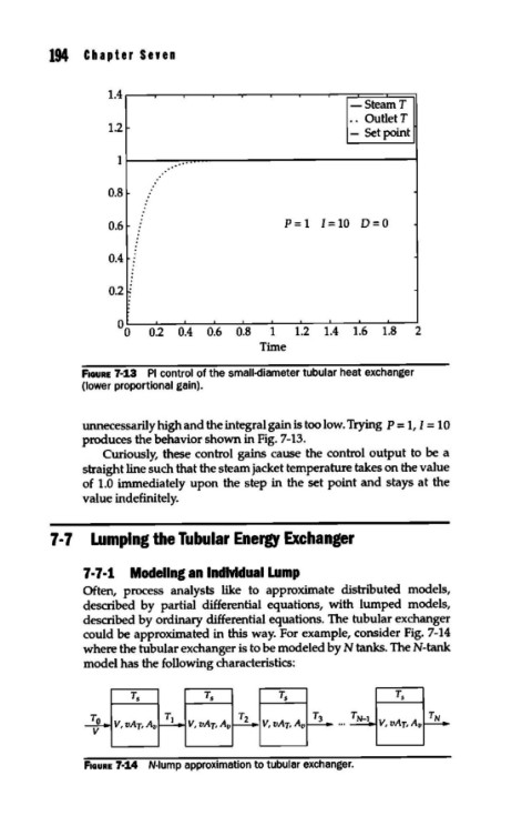
FIGURE 7-13 PI control of the small-diameter tubular heat exchanger
(lower proportional gain).
unnecessarily high and the integral gain is too low. Trying p = 1, I = 10
produces the behavior shown in Fig. 7-13.
Curiously, these control gains cause the control output to be a
straight line such that the steam jacket temperature takes on the value
of 1.0 immediately upon the step in the set point and stays at the
value indefinitely.
7 • 7 Lumping the Tubular Energy Exchanger
7 · 7 ·1 Modeling an Individual Lump
Often, process analysts like to approximate distributed models,
described by partial differential equations, with lumped models,
described by ordinary differential equations. The tubular exchanger
could be approximated in this way. For example, consider Fig. 7-14
where the tubular exchanger is to be modeled by N tanks. TheN-tank
model has the following characteristics:
FIGURE 7-14 N-lump approximation to tubular exchanger.