Page 519 - Practical Design Ships and Floating Structures
P. 519
494

              The numerical calculation is based on the software SHIPFLOW (FLOWTECH) which is a well-known
              software. The software employs the zonal approach that is the fluid domain around the hull is divided
              in three characteristic procedures:  the potential  flow, the boundary  layer and the true viscous flow
              analysis. In spite of  some restrictions on absolute values, the common  CFD techniques offer great
              possibilities as optimization tools for preliminary design.
              Therefore, the  first  objective  of  this  research  was  to  compare the  experimental and  numerical
              techniques,  to  get  acquainted  with  modem  numerical  tools  for  hull  design  and  to  verify  the
              optimization capabilities with some particular problems, for example, the choice of the stem wedge
              and the positioning of appendages


              2  THEORETICAL BACKGROUND
              The traditional procedure to estimate the  ship’s  resistance in calm  water is based of the Froude’s
              hypothesis which is given by:

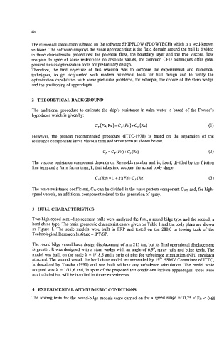
                                        C, (Fn, Re)= C, (Fn)+ C, (Re)                 (1)

              However,  the  present  recommended  procedure  (ITTC-1978) is  based  on  the  separation  of  the
              resistance components into a viscous term and wave term as shown below.

                                                    +
                                           C, = C, (Fn) C, (Re)                       0)
              The viscous resistance component depends on Reynolds number and is, itself, divided by the friction
              line term and a form factor term, k, that takes into account the actual body shape.
                                        C, (Rn) = (1 + R)(Fn). C, (Re)                (3)

              The wave resistance coefficient, CW can be divided in the wave pattern component Cwp and, for high-
              speed vessels, an additional component related to the generation of spray.


              3  HULL CHARACTERISTICS

              Two high-speed semi-displacement hulls were analyzed the first, a round bilge type and the second, a
              hard chine type. The main geometric characteristics are given on Table 1 and the body plans are shown
              in  Figure  1.  The  scale models  were  built  in  FRP  and  tested  on the 280,O m  towing tank of  the
              Technological Research Institute  - IPT/SP.
              The round bilge vessel has a design displacement of A 3 2 15 ton, but its final operational displacement
              is greater. It was designed with a stem wedge with an angle of 6.9’,  spray rails and bilge keels. The
              model was built on the scale h = 111 8,5 and a strip of pins for turbulence stimulation (NPL standard)
              attached. The second vessel, the hard chine model recommended by  19* HSMV Committee of ITTC,
              is described  by  Tanaka (1 990) and  was built without any turbulence stimulation. The model  scale
              adopted was h = 111 1,6 and, in spite of the proposed test conditions include appendages, these were
              not included but will be installed in fbture experiments.


              4  EXPERIMENTAL AND NUMERIC CONDITIONS
              The towing tests for the round-bilge models were carried on for a speed range of 0,25  < Fn  < 0,65

