Page 523 - Practical Design Ships and Floating Structures
P. 523

498


                 (%  L”)
                   .2n
                  .in
                   M
                   30
                   2.0
                   1Jl
                   M
                   -in
                  10.0
                   8.0
                   6.0
                   4.0
                   2.0
                   0.0
                    M   a2   a4             ”  ’.‘
                   rYod ,.m.drrW.-W”  rdw  Od  Fn Dd
                   O  M  PLk.5lgw  .Pl
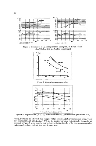
                       Figure 6: Comparison of CT, sinkage and trim among the 2 m IPTlST Model,
                                  13 m U.Tokyo (left) and 4 m SIU Model (right)
                                   or, OWP
                                    I m*


                                            ”.‘..(
                                    no
                                     0.2    a4     L.     a8     1.0
                                                              M
                                    Figure 7:  Comparison wave pattern Cwp


                                   040   045   050   055   060   065   070
                                                    _. -~       Fn
                                      [Gtiimi+Fij-   ‘CW k d  ‘CW  4
                Figure 8:  Comparison of CR, CW, CWK (form factor) and CWK-~, (form factor + spray factor) vs. F.

              Finally, to analyze the effects of stem wedges, wedges were included in the numerical model. These
              have a constant length ratio, Lw/Lsp = 7 % and the angles were varied systematically. The results are
              presented in Figure 9 where it can be clearly observed that the benefits of the stem wedges depend on
              wedge’s angle and are restricted for a specific speed range.
   518   519   520   521   522   523   524   525   526   527   528