
Page 521 - Practical Design Ships and Floating Structures
P. 521
496
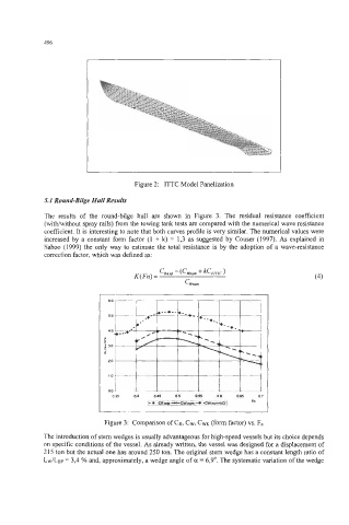
Figure 2: ITTC Model Panelization
5.1 Round-Bilge Hull Results
The results of the round-bilge hull are shown in Figure 3. The residual resistance coefficient
(witWwithout spray rails) from the towing tank tests are compared with the numerical wave resistance
coefficient. It is interesting to note that both curves profile is very similar. The numerical values were
increased by a constant form factor (1 + k) = 1,3 as suggested by Couser (1997). As explained in
Sahoo (1 999) the only way to estimate the total resistance is by the adoption of a wave-resistance
correction factor, which was defined as:
CReIp - (C~mrn + kc,,
K(Fn) = (4)
Cwnurn
r
6
Figure 3: Comparison of CR, CW, CWK (form factor) vs. F.
The introduction of stem wedges is usually advantageous for high-speed vessels but its choice depends
on specific conditions of the vessel. As already written, the vessel was designed for a displacement of
2 15 ton but the actual one has around 250 ton. The original stem wedge has a constant length ratio of
Lw/Lsp = 3,4 % and, approximately, a wedge angle of a = 6,9'. The systematic variation of the wedge