
Page 520 - Practical Design Ships and Floating Structures
P. 520
495
while the ITTC hard-chine model the range was 0,05 < Fn < 0,70 because of the limitation on the
carriage speed. Since then a new motor and control system was implemented and the high limit should
be increased to Fn = 1 ,O.
TABLE 1
SHIP’S AND MODEL’S GENERAL DIMENSIONS
Model I ITTC I RB
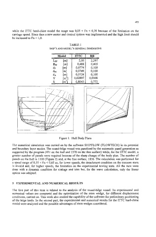
Figure 1: Hull Body Plans
The numerical simulation was carried on by the software SHIPFLOW (FLOWTECH) in its potential
and boundary layer modes. The round-bilge vessel was panelized by the automatic panel generation as
suggested by the program (45 1 on the hull and 1370 on the fiee surface) while, for the ITTC model, a
greater number of panels were required because of the sharp change of the body plan. The number of
panels on the hull is 1 100 (Figure 2) and, at the free surface, 1836. The calculation was performed for
a speed range of 0,35 < Fn < 0,65 as, for lower speeds, the detachment condition on the transom stem
is invalid and, for higher speeds, the limitation on the experimental towing tests. All the runs were
done with a dynamic condition for sinkage and trim but, for the wave calculation, only the linear
option was adopted.
5 EXPERIMENTAL AND NUMERICAL RESULTS
The first part of this item is related to the analysis of the round-bilge vessel. Its experimental and
numerical values are compared and the optimization of the stern wedge, for different displacement
conditions, carried on. This work also studied the capability of the software for preliminary positioning
of the bilge keels. In the second part, the experimental and numerical results for the ITTC hard-chine
model were analyzed and the possible advantages of stem wedges considered.