
Page 522 - Practical Design Ships and Floating Structures
P. 522
491
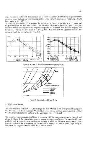
angle was carried on for both displacements and is shown in Figure 4. For the lower displacement the
optimum wedge angle agreed with the designed hull while, for the higher one, the wedge angle should
be increased to a = 10,9'.
To verify the potentialities of the software for preliminary studies the flow lines were calculated and
the positioning of the bilge keel checked. The results of this work is shown in Figure 5 were the
numerical results are compared with two previous options, one suggested by a Brazilian shipyard and
the second, obtained by flow analysis on towing tank. It is clear that the agreement between the
numerical result and towing tank are consistent.
Figure 4: CW vs. F, for different stern wedge angles (a)
I
Figure 5: Positioning of Bilge Keels
5.2 ITTC Model Results
The total resistance coefficient, CT , the sinkage and trim obtained in the towing tank are compared
with the values collected by Tanaka (1990) in Figure 6. The sinkage and trim agree reasonable well but
the total resistance coefficient are lower as the appendages were not included.
The numerical wave resistance coefficient is compared with the wave pattern term in Figure 7 and
plotted in Figure 8 for comparison with the residual resistance coefficient, CR, calculated by the
original Froude hypothesis. A second line was included in which the CW value was increased of the
form factor (1 +k) = 1,4 as suggested by Tanaka (1 990). As expected for this speed range the spray
component has a significant contribution on the total resistance.