
Page 527 - Practical Design Ships and Floating Structures
P. 527
502
an early design stage.
Every resistance prediction method requires also a reliable prediction of wetted surface area of the
vessel, to be able to predict not only the resistance coefficient but also the resistance force. Presented
method includes prediction of wetted surface area based on main geometric parameters using ANN
method. Again different networks are designed for each ship category.
ANN method offers the unique capability of easy adaptation to new data, which makes the developed
methods quasi-dynamic models. That means with the access to new measurement data, developed
networks can be upgraded with minimum amount of efforts. Networks are translated to DLLs that can
be implemented easily to existing software.
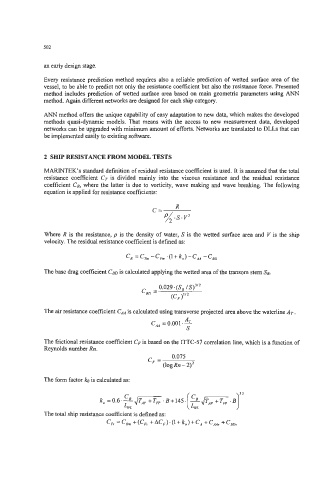
2 SHIP RESISTANCE FROM MODEL TESTS
MARINTEK’s standard definition of residual resistance coefficient is used. It is assumed that the total
resistance coefficient CT is divided mainly into the viscous resistance and the residual resistance
coefficient CR, where the Iatter is due to vorticity, wave making and wave breaking. The following
equation is applied for resistance coefficients:
R
c= A
P .s.p
Where R is the resistance, p is the density of water, S is the wetted surface area and V is the ship
velocity. The residual resistance coefficient is defined as:
c, =CTh -c, *(l+k,)-C, -c,
is
The base drag coefficient CBD calculated applying the wetted area of the transom stem SB.
The air resistance coefficient CAA is calculated using transverse projected area above the waterline AT.
4
c, = 0.001 .-
S
The frictional resistance coefficient CF is based on the ITTC-57 correlation line, which is a function of
Reynolds number Rn.
0.075
c, =
(log Rn - 2)’
The form factor ko is calculated as:
The total ship resistance coefficient is defined as:
C,, = C, + (C, + AC,) . (1 + k,) + C, + C,, + C,,