
Page 108 - Process Modelling and Simulation With Finite Element Methods
P. 108
Partial Differential Equations and the Finite Element Method 95
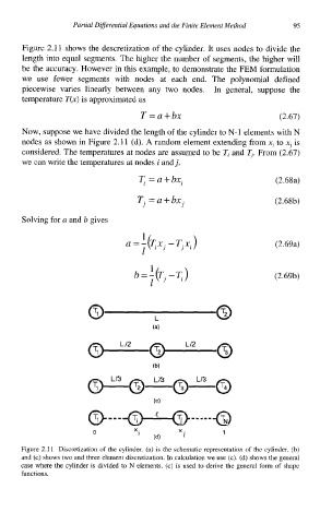
Figure 2.1 1 shows the descretization of the cylinder. It uses nodes to divide the
length into equal segments. The higher the number of segments, the higher will
be the accuracy. However in this example, to demonstrate the FEM formulation
we use fewer segments with nodes at each end. The polynomial defined
piecewise varies linearly between any two nodes. In general, suppose the
temperature T(x) is approximated as
T=a+bx (2.67)
Now, suppose we have divided the length of the cylinder to N-1 elements with N
nodes as shown in Figure 2.11 (d). A random element extending from .q to xj is
considered. The temperatures at nodes are assumed to be Ti and TJ. From (2.67)
we can write the temperatures at nodes i and j.
T, =a+bxi (2.68a)
Tj =a+bx. (2.68b)
J
Solving for a and b gives
a=- :( Tx. -T.x.) (2.69a)
J
11
1
b =-(T, -T,) (2.69b)
1
0 L 0
D X. ' (4 X. 1
I
Figure 2.1 1 Discretization of the cylinder. (a) is the schematic representation of the cylinder. (b)
and (c) shows two and three element discretization. In calculation we use (c). (d) shows the general
case where the cylinder is divided to N elements. (c) is used to derive the general form of shape
functions.