
Page 236 - Process Modelling and Simulation With Finite Element Methods
P. 236
Geometric Continuation 223
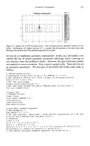
Contour. pressure (p) Max 91 5
86 91
15
65 18
, ,I
, , ,
1
0 1 2 3 4 5 Mm 0
Figure 6.5 Isobars for &=0.40 blockage factor. Note the high pressure gradients achieved in the
orifice. Furthermore, the highest pressure 91.3, is greater than the pressure at the inlet, due to the
blockage forcing fluid Out of the positions upstream of the plate.
So how do we implement geometric continuation? In this case, all models, even
without the use of nearby geometric parameters (blockage factor) converge in
one iteration, since the problem is linear. However, the grid refinement studies
are required to ensure resolution. First, export a model m-file. Then edit it to set
up geometric parameters. The first part of my MATLAB m-file script reads as
follows:
% FEMLAB Model M-file
% Generated 16-Apr-2002 20:25:17 by FEMLAB 2.2.0.181.
% WZ: Define a vector slot with a range of blockage factors
slot=[0.95:-0.05:0.25];
% WZ: Set up storage
output=zeros (length(s1ot) ,5) ;
% WZ: Now loop around the whole FEMLAB model m-file with j
for j=1 :length (slot)
flclear fem
% FEMLAB Version
clear vrsn;
vrsn.name='FEMLAB 2.2';
vrsn. maj or=O;
vrsn.build=lSl;
fem.version=vrsn;
% Recorded command sequence
% New aeometrv 1
fem.sdim=( nxn: Iyl};
% WZ: Key section. Note that I have edited occurrences of 0.95 for
% notch and inserted the variable slot (j
)
% Geometry
clear s c p
p=[O 0 2 2 2.05 2.05 5 5;O 1 ...
slot(j) 1 slotij) 1 0 11;
rb={1:8,[1 12 3 3 5 6 7;2 7 4 4 5 6 8 81,zeros(3,0),zeros(4,0)};
,
wt= {zeros (I,o) , ones (2,~) zeros (3,0) , zeros (4,0) } ;
% The femlab recorded command sequence continues up to ...