Page 49 - Process Modelling and Simulation With Finite Element Methods
P. 49

36          Process Modelling and Simulation with Finite Element Methods


                                 dY
                                - z(x)
                                    =
                                 dx
                                 dz
                                - r(x)- q(x)z(x)
                                    =
                                 dx
         Each of these ODEs can be numerically integrated by time marching methods as
         in (1.10) or (1.1  l), simultaneously.  A simple example is
                                     d 'u
                                    -+u=o                            (1.13)
                                     dt2

         Reduction of order yields two first order ODEs:
                                     du
                                        1-   u2
                                      dt
                                                                     (1.14)
                                     du2
                                      dt   - u1
         Taking the initial condition to be u,=l and u2=0, we can now set up a O-D spatial
         system to integrate this coupled set of ODEs.
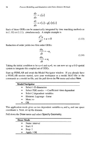
         Start up FEMLAB and await the Model Navigator window.  If you already have
         a FEMLAB  session started, save your  workspace as a model MAT-file or the
         commands as a model m-file, and the pull down the file menu and select New.

                   Model Navigator
                          Select l-D dimension
                          Select PDE modes + Coefficient+time dependent
                          Select 2 dependent variables
                          Element: Lagrange - linear
                      0   More>>
                          OK
                      0
         This application mode gives us two dependent variables uI and u2 and one space
         coordinate x. Next, set up the domain.
         Pull down the Draw menu and select Specify Geometry.

                   Draw Mode
                          Name: interval
                          start: 0
                          stop: 1
                          ApplylOK
   44   45   46   47   48   49   50   51   52   53   54