
Page 102 - Rapid Learning in Robotics
P. 102
88 Extensions to the Standard PSOM Algorithm
not use any topological information. The differences are significant:
the required training data set for the LLM network is much larger,
here 2500 points versus 25 data for the PSOM network (factor 100);
the PSOM can employ the self-organizing adaption rule Eq. 3.10 on
a much smaller data set (25), or it can be instantly constructed if the
sampling structure is known apriori (rapid-learning);
the obtained degree of continuity and accuracy compares very favor-
ably (Fig. 6.8 and Fig. 6.7). The PSOM approach does not need any
extra heuristics to overcome the discrete nature of the local expert
structure, which is visible in the discontinuities at the cell borders in
Fig. 6.8.
6.6 RLC-Circuit Example
In this section a four-dimensional mapping example is presented. The pur-
pose of this exercise is to see (i) to what extent the various m dimen-
sional PSOM networks approximate the underlying functions; (ii) how
this compares to the work of Friedman (1991) investigating the same pa-
rameter regime; (iii) to yield insight into the variable relationships.
U
I
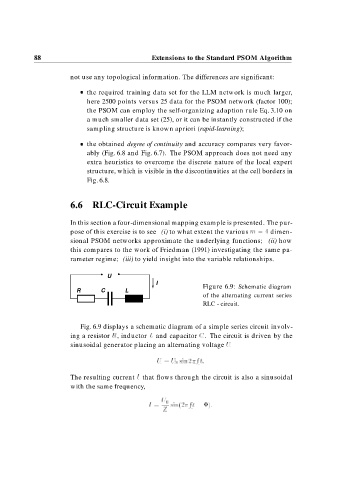
Figure 6.9: Schematic diagram
R C L
of the alternating current series
RLC - circuit.
Fig. 6.9 displays a schematic diagram of a simple series circuit involv-
ing a resistor R, inductor L and capacitor C. The circuit is driven by the
sinusoidal generator placing an alternating voltage U
U U sin
f t
The resulting current I that flows through the circuit is also a sinusoidal
with the same frequency,
U
I sin
f t
Z