
Page 151 - Rashid, Power Electronics Handbook
P. 151
140 Y.-S. Lee and M. Chow
FIGURE 10.1 A single-phase half-wave recti®er with resistive load.
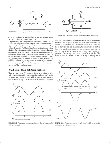
FIGURE 10.3 Full-wave recti®er with center-tapped transformer.
current waveforms of resistive load R and the voltage wave-
form of diode D are shown in Fig. 10.2.
with the associated half of the transformer, acts as a half-wave
By observing the voltage waveform of diode D in Fig. 10.2, it
recti®er. The outputs of the two half-wave recti®ers are
is clear that the peak inverse voltage (PIV) of diode D is equal to
combined to produce full-wave recti®cation in the load. As
V during the negative half-cycle of the transformer secondary far as the transformer is concerned, the dc currents of the two
m
voltage. Hence the Peak Repetitive Reverse Voltage (V RRM ) rating half-wave recti®ers are equal and opposite, such that there is
of diode D must be chosen to be higher than V to avoid reverse
m
breakdown. In the positive half-cycle of the transformer second- no dc current for creating a transformer core saturation
problem. The voltage and current waveforms of the full-
ary voltage, diode D has a forward current which is equal to the wave recti®er are shown in Fig. 10.4. By observing diode
load current and, therefore, the Peak Repetitive Forward Current
(I ) rating of diode D must be chosen to be higher than the
FRM
peak load current V =R, in practice. In addition, the transfor-
m
mer has to carry a dc current that may result in a dc saturation
problem of the transformer core.
10.2.2 Single-Phase Full-Wave Rectifiers
There are two types of single-phase full-wave recti®er, namely,
full-wave recti®ers with center-tapped transformer and bridge
recti®ers. A full-wave recti®er with a center-tapped transfor-
mer is shown in Fig. 10.3. It is clear that each diode, together
FIGURE 10.2 Voltage and current waveforms of the half-wave recti®er FIGURE 10.4 Voltage and current waveforms of the full-wave recti®er
with resistive load. with center-tapped transformer.