
Page 156 - Rashid, Power Electronics Handbook
P. 156
10 Diode Recti®ers 145
10.3.1 Three-Phase Star Rectifiers
10.3.1.1 Basic Three-Phase Star Rectifier Circuit
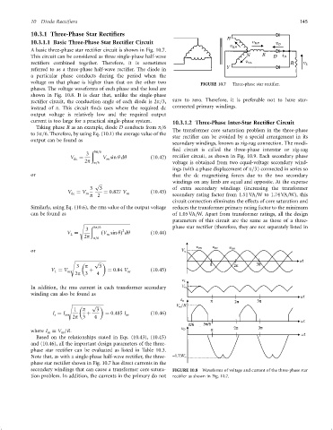
A basic three-phase star recti®er circuit is shown in Fig. 10.7.
This circuit can be considered as three single-phase half-wave
recti®ers combined together. Therefore, it is sometimes
referred to as a three-phase half-wave recti®er. The diode in
a particular phase conducts during the period when the
voltage on that phase is higher than that on the other two FIGURE 10.7 Three-phase star recti®er.
phases. The voltage waveforms of each phase and the load are
shown in Fig. 10.8. It is clear that, unlike the single-phase
recti®er circuit, the conduction angle of each diode is 2p=3, sum to zero. Therefore, it is preferable not to have star-
instead of p. This circuit ®nds uses where the required dc connected primary windings.
output voltage is relatively low and the required output
current is too large for a practical single-phase system. 10.3.1.2 Three-Phase Inter-Star Rectifier Circuit
Taking phase R as an example, diode D conducts from p=6
The transformer core saturation problem in the three-phase
to 5p=6. Therefore, by using Eq. (10.1) the average value of the
star recti®er can be avoided by a special arrangement in its
output can be found as
secondary windings, known as zig-zag connection. The modi-
®ed circuit is called the three-phase interstar or zig-zag
ð 5p=6
3
V ¼ V sin y dy ð10:42Þ recti®er circuit, as shown in Fig. 10.9. Each secondary phase
dc
m
2p p=6 voltage is obtained from two equal-voltage secondary wind-
ings (with a phase displacement of p=3) connected in series so
or that the dc magnetizing forces due to the two secondary
windings on any limb are equal and opposite. At the expense
p
3 3 of extra secondary windings (increasing the transformer
V ¼ V m ¼ 0:827 V m ð10:43Þ
dc
p 2 secondary rating factor from 1.51 VA=W to 1.74 VA=W), this
circuit connection eliminates the effects of core saturation and
Similarly, using Eq. (10.6), the rms value of the output voltage reduces the transformer primary rating factor to the minimum
can be found as of 1.05 VA=W. Apart from transformer ratings, all the design
parameters of this circuit are the same as those of a three-
s
ð 5p=6 phase star recti®er (therefore, they are not separately listed in
3 2
V ¼ ðV sin yÞ dy ð10:44Þ
m
L
2p p=6
or
p
s
3 p 3
V ¼ V m þ ¼ 0:84 V m ð10:45Þ
L
2p 3 4
In addition, the rms current in each transformer secondary
winding can also be found as
s
p
1 p 3
I ¼ I m þ ¼ 0:485 I m ð10:46Þ
s
2p 3 4
where I ¼ V =R.
m
m
Based on the relationships stated in Eqs. (10.43), (10.45)
and (10.46), all the important design parameters of the three-
phase star recti®er can be evaluated as listed in Table 10.3.
Note that, as with a single-phase half-wave recti®er, the three-
phase star recti®er shown in Fig. 10.7 has direct currents in the
secondary windings that can cause a transformer core satura- FIGURE 10.8 Waveforms of voltage and current of the three-phase star
tion problem. In addition, the currents in the primary do not recti®er as shown in Fig. 10.7.