
Page 161 - Rashid, Power Electronics Handbook
P. 161
150 Y.-S. Lee and M. Chow
TABLE 10.4 Important design parameters of six-phase recti®er circuits with resistive load
Six-Phase Star Recti®er Six-Phase Series Bridge Six-Phase Parallel Bridge
Recti®er Recti®er (With Inter-Phase
Transformer)
Peak repetitive reverse voltage V RRM 2.09 V dc 0.524 V dc 1.05 V dc
Rms input voltage per transformer leg V s 0.74 V dc 0.37 V dc 0.715 V dc
Diode average current I FðAVÞ 0.167 I dc 0.333 I dc 0.167 I dc
Peak repetitive forward current I FRM 6.28 I FðAVÞ 3.033 I FðAVÞ 3.14 I FðAVÞ
Diode rms current I FðRMSÞ 0.409 I dc 0.576 I dc 0.409 I dc
2.45 1.73 2.45
Form factor of diode current I FðRMSÞ =I FðAVÞ
Recti®cation ratio 0.998 1.00 1.00
Form factor 1.0009 1.00005 1.00005
Ripple factor 0.042 0.01 0.01
Transformer rating primary VA 1.28 P dc 1.01 P dc 1.01 P dc
Transformer rating secondary VA 1.81 P dc 1.05 P dc 1.05 P dc
Output ripple frequency f r 6 f i 12 f i 12 f i
in opposite directions in the interphase transformer winding)
produce no dc magnetization current.
All the important design parameters of the six-phase paral-
lel recti®ers with interphase transformer are also listed in Table
10.4.
10.5 Filtering Systems in Rectifier
Circuits
Filters are commonly employed in recti®er circuits for
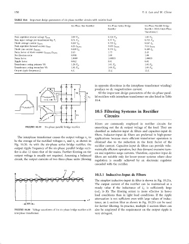
FIGURE 10.19 Six-phase parallel bridge recti®er. smoothing out the dc output voltage of the load. They are
classi®ed as inductor-input dc ®lters and capacitor-input dc
®lters. Inductor-input dc ®lters are preferred in high-power
The interphase transformer causes the output voltage v to applications because more ef®cient transformer operation is
L
be the average of the recti®ed voltages v and v as shown in obtained due to the reduction in the form factor of the
1
2
Fig. 10.20. As with the six-phase series bridge recti®er, the recti®er current. Capacitor-input dc ®lters can provide volu-
output ripple frequency of the six-phase parallel bridge recti- metrically ef®cient operation, but they demand excessive turn-
®er is also 12 times that of the mains. Further ®ltering on the on and repetitive surge currents. Therefore, capacitor-input dc
output voltage is usually not required. Assuming a balanced ®lters are suitable only for lower-power systems where close
circuit, the output currents of two three-phase units (¯owing regulation is usually achieved by an electronic regulator
cascaded with the recti®er.
10.5.1 Inductive-Input dc Filters
The simplest inductive-input dc ®lter is shown in Fig. 10.21a.
The output current of the recti®er can be maintained at a
steady value if the inductance of L f is suf®ciently large
ðoL RÞ. The ®ltering action is more effective in heavy
f
load conditions than in light load conditions. If the ripple
attenuation is not suf®cient even with large values of induc-
tance, an L-section ®lter as shown in Fig. 10.21b can be used
for further ®ltering. In practice, multiple L-section ®lters can
FIGURE 10.20 Voltage waveforms of the six-phase bridge recti®er with also be employed if the requirement on the output ripple is
interphase transformer. very stringent.