Page 162 - Rashid, Power Electronics Handbook
P. 162

10  Diode Recti®ers                                                                                 151


                 FIGURE 10.21  Inductive-input dc ®lters. (a) Simplest inductive-input
                 dc ®lter; (b) L-section ®lter.


                   For the simple inductive-input dc ®lter shown in Fig.
                 10.21a, the ripple is reduced by the factor

                                  v         R
                                   o
                                    ¼ q   ð10:64Þ
                                  v L    2         2
                                        R þð2pf L Þ
                                               r f
                 where v is the ripple voltage before ®ltering, v is the ripple
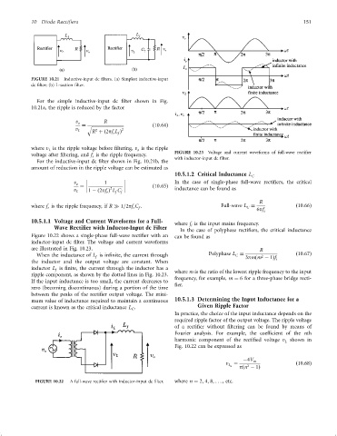
                        L                               o             FIGURE 10.23  Voltage and current waveforms of full-wave recti®er
                 voltage after ®ltering, and f is the ripple frequency.
                                        r                             with inductor-input dc ®lter.
                   For the inductive-input dc ®lter shown in Fig. 10.21b, the
                 amount of reduction in the ripple voltage can be estimated as
                                                                      10.5.1.2 Critical Inductance L C

                                 v o  ¼       1               ð10:65Þ  In the case of single-phase full-wave recti®ers, the critical
                                              2
                                 v      1 ÿð2pf Þ L C                 inductance can be found as
                                  L          r  f  f
                                                                                                     R
                 where f is the ripple frequency, if R   1=2pf C :                     Full-wave L ¼               ð10:66Þ
                                                                                                C
                                                         f
                                                       r
                       r
                                                                                                    6pf i
                 10.5.1.1 Voltage and Current Waveforms for a Full-   where f is the input mains frequency.
                          Wave Rectifier with Inductor-Input dc Filter       i
                                                                        In the case of polyphase recti®ers, the critical inductance
                 Figure 10.22 shows a single-phase full-wave recti®er with an  can be found as
                 inductor-input dc ®lter. The voltage and current waveforms
                 are illustrated in Fig. 10.23.                                                      R
                   When the inductance of L is in®nite, the current through        Polyphase L ¼  3pmðm ÿ 1Þf      ð10:67Þ
                                                                                            C
                                                                                                      2
                                         f
                 the inductor and the output voltage are constant. When                                    i
                 inductor L is ®nite, the current through the inductor has a  where m is the ratio of the lowest ripple frequency to the input
                          f
                 ripple component, as shown by the dotted lines in Fig. 10.23.
                                                                      frequency, for example, m ¼ 6 for a three-phase bridge recti-
                 If the input inductance is too small, the current decreases to
                                                                      ®er.
                 zero (becoming discontinuous) during a portion of the time
                 between the peaks of the recti®er output voltage. The mini-
                 mum value of inductance required to maintain a continuous  10.5.1.3 Determining the Input Inductance for a
                 current is known as the critical inductance L .              Given Ripple Factor
                                                      C
                                                                      In practice, the choice of the input inductance depends on the
                                                                      required ripple factor of the output voltage. The ripple voltage
                                                                      of a recti®er without ®ltering can be found by means of
                                                                      Fourier analysis. For example, the coef®cient of the nth
                                                                      harmonic component of the recti®ed voltage v shown in
                                                                                                              L
                                                                      Fig. 10.22 can be expressed as
                                                                                               ÿ4V m
                                                                                         v  ¼                      ð10:68Þ
                                                                                          L n    2
                                                                                              pðn ÿ 1Þ
                   FIGURE 10.22  A full-wave recti®er with inductor-input dc ®lter.  where n ¼ 2; 4; 8; ... , etc.
   157   158   159   160   161   162   163   164   165   166   167