Page 163 - Rashid, Power Electronics Handbook
P. 163

152                                                                                 Y.-S. Lee and M. Chow

                 The dc component of the recti®er voltage is given by Eq.
               (10.5). Therefore, in addition to Eq. (10.27), the ripple factor
               can also be expressed as

                                   s 
                                                   2
                                       P      1
                              RF ¼   2                      ð10:69Þ
                                             2
                                      n¼2;4;8 n ÿ 1
               Considering only the lowest-order harmonic (n ¼ 2), the
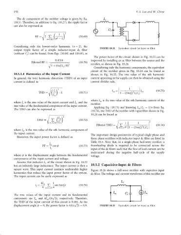
                                                                          FIGURE 10.24  Equivalent circuit for input ac ®lter.
               output ripple factor of a simple inductor-input dc ®lter
               (without C ) can be found, from Eqs. (10.64) and (10.69), as
                        f
                                                                      The power factor of the circuit shown in Fig. 10.22 can be
                                            0:4714                  improved by installing an ac ®lter between the source and the
                            Filtered RF ¼ q   ð10:70Þ
                                                     2              recti®er, as shown in Fig. 10.24.
                                         1 þð4pf L =RÞ
                                               i f
                                                                      Considering only the harmonic components, the equivalent
                                                                    circuit of the recti®er given in Fig. 10.24 can be found as
               10.5.1.4 Harmonics of the Input Current              shown in Fig. 10.25. The rms value of the nth harmonic
               In general, the total harmonic distortion (THD) of an input  current appearing in the supply can then be obtained using the
               current is de®ned as                                 current-divider rule,
                                       s 
                                             2                                                1
                                           I s                                    I ¼                  I         ð10:75Þ
                                                                                   sn
                                                                                                 2
                                THD ¼         ÿ1            ð10:71Þ                       1 ÿð2npf Þ L C    rn
                                          I s1                                                  i  i  i
                                                                    where I is the rms value of the nth harmonic current of the
                                                                          rn
               where I is the rms value of the input current and I and the
                      s                                   s1        recti®er.
               rms value of the fundamental component of the input current.
                                                                      Applying Eq. (10.73) and knowing I =I ¼ 1=n from Eq.
                                                                                                    rn
                                                                                                       r1
               The THD can also be expressed as
                                                                    (10.74), the THD of the recti®er with input ®lter shown in Fig.
                                                                    10.24 can be found as
                                      s 
                                                 2
                                         P    I sn
                               THD ¼                        ð10:72Þ                  s 
                                        n¼2;3;4 I s1                                    P 1         1          2
                                                                        Filtered THD ¼                           ð10:76Þ
                                                                                                       2
                                                                                       n¼3;5 n 2    1 ÿð2npf Þ L C i
                                                                                                         i
                                                                                                      i
               where I is the rms value of the nth harmonic component of
                      sn
               the input current.
                                                                    The important design parameters of typical single-phase and
                 Moreover, the input power factor is de®ned as
                                                                    three-phase recti®ers with inductor-input dc ®lter are listed in
                                                                    Table 10.5. Note that, in a single-phase half-wave recti®er, a
                                        I s1
                                   PF ¼   cos f             ð10:73Þ  freewheeling diode is required to be connected across the
                                        I s                         input of the dc ®lters such that the ¯ow of load current can be
                                                                    maintained during the negative half-cycle of the supply
               where f is the displacement angle between the fundamental  voltage.
               components of the input current and voltage.
                 Assume that inductor L of the circuit shown in Fig. 10.22
                                     f
               has an in®nitely large inductance. The input current is then a  10.5.2 Capacitive-Input dc Filters
               square wave. This input current contains undesirable higher  Figure 10.26 shows a full-wave recti®er with capacitor-input
               harmonics that reduce the input power factor of the system.  dc ®lter. The voltage and current waveforms of this recti®er are
               The input current can be easily expressed as
                                  4I m  P 1
                              i ¼          sin 2npf t       ð10:74Þ
                               s                  i
                                   p n¼1;3;5 n
               The rms values of the input current and its fundamental
                                          p
                                           
               component are I m  and 4I =ðp 2Þ, respectively. Therefore,
                                      m
               the THD of the input current of this circuit is 0.484. As the
                                                         p
                                                          
               displacement angle f ¼ 0, the power factor is 4=ðp 2Þ¼ 0:9.  FIGURE 10.25  Equivalent circuit for input ac ®lter.
   158   159   160   161   162   163   164   165   166   167   168