
Page 164 - Rashid, Power Electronics Handbook
P. 164
10 Diode Recti®ers 153
TABLE 10.5 Important design parameters of typical recti®er circuits with inductor-input dc ®lter
Full-wave Full-Wave Three-Phase Three-Phase Three-Phase
Recti®er Bridge Star Bridge Double-Star
With Center- Recti®er Recti®er Recti®er Recti®er With
Tapped Interphase
Transformer Transformer
Peak repetitive reverse voltage V RRM 3.14 V dc 1.57 V dc 2.09 V dc 1.05 V dc 2.42 V dc
Rms input voltage per transformer leg V s 1.11 V dc 1.11 V dc 0.885 V dc 0.428 V dc 0.885 V dc
Diode average current I FðAVÞ 0.5 I dc 0.5 I dc 0.333 I dc 0.333 I dc 0.167 I dc
Peak repetitive forward current I FRM 2.00 I FðAVÞ 2.00 I FðAVÞ 3.00 I FðAVÞ 3.00 I FðAVÞ 3.00 I FðAVÞ
Diode rms current I FðRMSÞ 0.707 I dc 0.707 I dc 0.577 I dc 0.577 I dc 0.289 I dc
1.414 1.414 1.73 1.73 1.73
Form factor of diode current I FðRMSÞ =I FðAVÞ
Transformer rating primary VA 1.11 P dc 1.11 P dc 1.21 P dc 1.05 P dc 1.05 P dc
Transformer rating secondary VA 1.57 P dc 1.11 P dc 1.48 P dc 1.05 P dc 1.48 P dc
Output ripple frequency f r 2 f i 2 f i 3 f i 6 f i 6 f i
Ripple component V r at
(a) fundamental 0.667 V dc 0.667 V dc 0.250 V dc 0.057 V dc 0.057 V dc
(b) second harmonic 0.133 V dc 0.133 V dc 0.057 V dc 0.014 V dc 0.014 V dc
(c) third harmonic of the ripple frequency 0.057 V dc 0.057 V dc 0.025 V dc 0.006 V dc 0.006 V dc
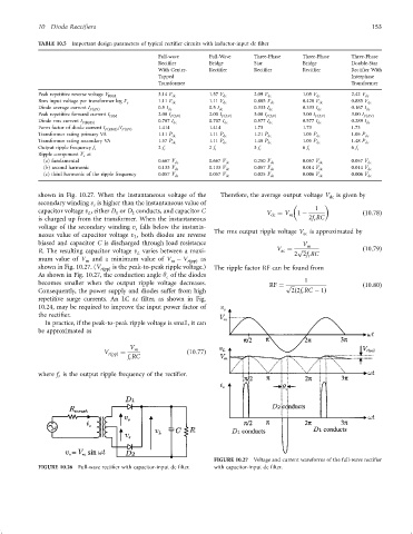
shown in Fig. 10.27. When the instantaneous voltage of the Therefore, the average output voltage V is given by
dc
secondary winding v is higher than the instantaneous value of
s
capacitor voltage v , either D or D conducts, and capacitor C V ¼ V m 1 ÿ 1 ð10:78Þ
L
1
2
dc
is charged up from the transformer. When the instantaneous 2f RC
r
voltage of the secondary winding v falls below the instanta-
s
ac
neous value of capacitor voltage v , both diodes are reverse The rms output ripple voltage V is approximated by
L
biased and capacitor C is discharged through load resistance V m
R. The resulting capacitor voltage v varies between a maxi- V ¼ p ð10:79Þ
ac
2 2f RC
L
mum value of V m and a minimum value of V ÿ V rðppÞ as r
m
shown in Fig. 10.27. (V rðppÞ is the peak-to-peak ripple voltage.) The ripple factor RF can be found from
As shown in Fig. 10.27, the conduction angle y of the diodes
c
becomes smaller when the output ripple voltage decreases. RF ¼ p 1 ð10:80Þ
Consequently, the power supply and diodes suffer from high 2ð2f RC ÿ 1Þ
r
repetitive surge currents. An LC ac ®lter, as shown in Fig.
10.24, may be required to improve the input power factor of
the recti®er.
In practice, if the peak-to-peak ripple voltage is small, it can
be approximated as
V m
V rðppÞ ¼ ð10:77Þ
f RC
r
where f is the output ripple frequency of the recti®er.
r
FIGURE 10.27 Voltage and current waveforms of the full-wave recti®er
FIGURE 10.26 Full-wave recti®er with capacitor-input dc ®lter. with capacitor-input dc ®lter.