
Page 160 - Rashid, Power Electronics Handbook
P. 160
10 Diode Recti®ers 149
or individual bridge recti®er) to 1%. The combined bridge
recti®er is referred to as a six-phase series bridge recti®er.
6 1 In the six-phase series bridge recti®er shown in Fig. 10.18,
V ¼ V m ¼ 0:955 V m ð10:54Þ
dc
p 2 let V m be the peak voltage of the delta-connected secondary.
The peak voltage between the lines of the star-connected
Similarly, the rms value of the output voltage can be found as secondary is also V . The peak voltage across the load,
m
denoted as V , is equal to 2 V cosðp=12Þ or 1:932 V m
m
m
s
ð 2p=3 because there is p=6-phase displacement between the second-
6 2
V ¼ ðV sin yÞ dy ð10:55Þ aries. The ripple frequency is 12 times the mains frequency.
L
m
2p p=3 The average value of the output voltage can be found as
or 12 ð 7p=12
V ¼ V sin y dy ð10:58Þ
dc
m
p
s p 5p=12
6 p 3
V ¼ V m þ ¼ 0:956 V m ð10:56Þ
L
2p 6 4 or
p
In addition, the rms current in each transformer secondary 12 3 ÿ 1
V ¼ V m p ¼ 0:98862 V m ð10:59Þ
dc
winding can be found as p 2 2
p
s The rms value of the output voltage can be found as
1 p 3
I ¼ I þ ¼ 0:39 I ð10:57Þ
s m m s
2p 6 4 ð 7p=12
12 2
V ¼ ðV sin yÞ dy ð10:60Þ
L 2p m
where I ¼ V =R. 5p=12
m
m
Based on the relationships stated in Eqs. (10.55), (10.56),
or
and (10.57), all the important design parameters of the six-
phase star recti®er can be evaluated, as listed in Table 10.4 s
(given at the end of Section 10.4.3). 12 p 1
V ¼ V þ ¼ 0:98867 V ð10:61Þ
L m m
2p 12 4
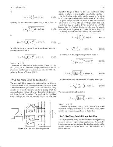
10.4.2 Six-Phase Series Bridge Rectifier The rms current in each transformer secondary winding is
The star- and delta-connected secondaries have an inherent s
4 p 1
p=6-phase displacement between their output voltages. When I ¼ I m þ ¼ 0:807 I m ð10:62Þ
s
a star-connected bridge recti®er and a delta-connected bridge p 12 4
recti®er are connected in series as shown in Fig. 10.18, the
combined output voltage will have a doubled ripple frequency The rms current through a diode is
(12 times that of the mains). The ripple of the combined
s
output voltage will also be reduced from 4.2% (for each 2 p 1
I ¼ I þ ¼ 0:57 I ð10:63Þ
s m m
p 12 4
where I ¼ V =R.
m m
Based on Eqs. (10.59), (10.61), (10.62), and (10.63), all the
important design parameters of the six-phase series bridge
recti®er can be evaluated, as listed in Table 10.4.
10.4.3 Six-Phase Parallel Bridge Rectifier
The six-phase series bridge recti®er described in the preceding
is useful for high-output voltage applications. However, for
high-output current applications, the six-phase parallel bridge
recti®er (with an interphase transformer) shown in Fig. 10.19
FIGURE 10.18 Six-phase series bridge recti®er. should be used.