
Page 155 - Rashid, Power Electronics Handbook
P. 155
144 Y.-S. Lee and M. Chow
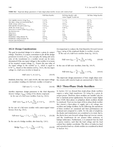
TABLE 10.2 Important design parameters of basic single-phase recti®er circuits with resistive load
Half-Wave Recti®er Full-Wave Recti®er with Full-Wave Bridge Recti®er
Center-Tapped Transformer
Peak repetitive reverse voltage V RRM 3.14 V dc 3.14 V dc 1.57 V dc
Rms input voltage per transformer leg V s 2.22 V dc 1.11 V dc 1.11 V dc
Diode average current I FðAVÞ 1.00 I dc 0.50 I dc 0.50 I dc
Peak repetitive forward current I FRM 3.14 I FðAVÞ 1.57 I FðAVÞ 1.57 I FðAVÞ
Diode rms current I FðRMSÞ 1.57 I dc 0.785 I dc 0.785 I dc
1.57 1.57 1.57
Form factor of diode current I FðRMSÞ =I FðAVÞ
Recti®cation ratio 0.405 0.81 0.81
Form factor 1.57 1.11 1.11
Ripple factor 1.21 0.482 0.482
Transformer rating primary VA 2.69 P dc 1.23 P dc 1.23 P dc
Transformer rating secondary VA 3.49 P dc 1.75 P dc 1.23 P dc
Output ripple frequency f r 1 f i 2 f i 2 f i
10.2.4 Design Considerations It is important to evaluate the Peak Repetitive Forward Current
(I FRM ) rating of the employed diodes in recti®er circuits.
The goal in practical design is to achieve a given dc output
In the case of a half-wave recti®er, from Eq. (10.13),
voltage. Therefore, it is more convenient to put all the design
parameters in terms of V . For example, the rating and turns
dc
ratio of the transformer in a recti®er circuit can be easily Half-wave I FRM ¼ V m ¼ I dc ¼ 3:41I dc ð10:40Þ
determined if the rms input voltage to the recti®er is in terms R 0:318
of the required output voltage V . Denote the rms value of
dc
the input voltage to the recti®er as V , which is equal to In the case of full-wave recti®ers, from Eq. (10.15),
s
0:707 V . Based on this relation and Eq. (10.3), the rms input
m
voltage to a half-wave recti®er is found as V I
Full-wave I FRM ¼ m ¼ dc ¼ 1:57I dc ð10:41Þ
R 0:636
Half-wave V ¼ 2:22 V dc ð10:35Þ
s
The important design parameters of basic single-phase recti-
Similarly, from Eqs. (10.5) and (10.29), the rms input voltage ®er circuits with resistive loads are summarized in Table 10.2.
per secondary winding of a full-wave recti®er is found as
Full-wave V ¼ 1:11 V ð10:36Þ 10.3 Three-Phase Diode Rectifiers
s dc
Another important design parameter is the Peak Repetitive In Section 10.2 we showed that single-phase diode recti®ers
Reverse Voltage (V RRM ) rating of the diodes employed. require a rather high transformer VA rating for a given dc
In the case of a half-wave recti®er, from Eq. (10.3), output power. Therefore, these recti®ers are suitable only for
low to medium power applications. For power output higher
than 15 kW, three-phase or polyphase diode recti®ers should
V dc
Half-wave V RRM ¼ V ¼ ¼ 3:14 V dc ð10:37Þ be employed. There are two types of three-phase diode recti®er
m
0:318
that convert a three-phase ac supply into a dc voltage, star
recti®ers and bridge recti®ers. In the following, the operations
In the case of a full-wave recti®er with center-tapped trans-
of these recti®ers are examined and their performances are
former, from Eq. (10.5),
analyzed and compared in a table. For the sake of simplicity,
the diodes and transformers are considered to be ideal, that is,
V dc
Full-wave V RRM ¼ 2 V ¼ 2 ¼ 3:14 V dc ð10:38Þ the diodes have zero forward voltage drop and reverse current,
m
0:636
and the transformers do not possess either resistance or
leakage inductance. Furthermore, it is assumed that the load
In the case of a bridge recti®er, also from Eq. (10.5), is purely resistive, such that the load voltage and the load
current have similar waveforms. The effects of inductive load
V dc and capacitive load on a diode recti®er are considered in detail
Bridge V RRM ¼ V ¼ ¼ 1:57 V dc ð10:39Þ
m
0:636 in Section 10.5.