
Page 157 - Rashid, Power Electronics Handbook
P. 157
146 Y.-S. Lee and M. Chow
TABLE 10.3 Important design parameters of three-phase recti®er circuits with resistive load
Three-Phase Star Recti®er Three-Phase Double-Star Recti®er Three-Phase Bridge Recti®er
With Inter-Phase Transformer
Peak repetitive reverse voltage V RRM 2.092 V dc 1.06 V dc 1.05 V dc
Rms input voltage per transformer leg V s 0.855 V dc 0.855 V dc 0.428 V dc
Diode average current I FðAVÞ 0.333 I dc 0.167 I dc 0.333 I dc
Peak repetitive forward current I FRM 3.63 I FðAVÞ 3.15 I FðAVÞ 3.14 I FðAVÞ
Diode rms current I FðRMSÞ 0.587 I dc 0.293 I dc 0.579 I dc
1.76 1.76 1.74
Form factor of diode current I FðRMSÞ =I FðAVÞ
Recti®cation ratio 0.968 0.998 0.998
Form factor 1.0165 1.0009 1.0009
Ripple factor 0.182 0.042 0.042
Transformer rating primary VA 1.23 P dc 1.06 P dc 1.05 P dc
Transformer rating secondary VA 1.51 P dc 1.49 P dc 1.05 P dc
Output ripple frequency f r 3 f i 6 f i 6 f i
FIGURE 10.9 Three-phase inter-star recti®er.
Table 10.3). Furthermore, a star-connected primary winding
with no neutral connection is equally permissible because the
sum of all primary phase currents is zero at all times.
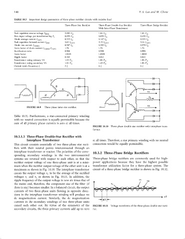
FIGURE 10.10 Three-phase double-star recti®er with interphase trans-
former.
10.3.1.3 Three-Phase Double-Star Rectifier with
Interphase Transformer at all times. Therefore, a star primary winding with no neutral
This circuit consists essentially of two three-phase star recti- connection would be equally permissible.
®ers with their neutral points interconnected through an
interphase transformer or reactor. The polarities of the corre- 10.3.2 Three-Phase Bridge Rectifiers
sponding secondary windings in the two interconnected
systems are reversed with respect to each other, so that the Three-phase bridge recti®ers are commonly used for high-
recti®er output voltage of one three-phase unit is at a mini- power applications because they have the highest possible
mum when the recti®er output voltage of the other unit is at a transformer utilization factor for a three-phase system. The
maximum as shown in Fig. 10.10. The interphase transformer circuit of a three-phase bridge recti®er is shown in Fig. 10.12.
causes the output voltage v to be the average of the recti®ed
L
voltages v and v as shown in Fig. 10.11. In addition, the
1
2
ripple frequency of the output voltage is now six times that of
the mains and, therefore, the component size of the ®lter (if
there is any) becomes smaller. In a balanced circuit, the output
currents of two three-phase units ¯owing in opposite direc-
tions in the interphase transformer winding will produce no
dc magnetization current. Similarly, the dc magnetization
currents in the secondary windings of two three-phase units
cancel each other out. By virtue of the symmetry of the FIGURE 10.11 Voltage waveforms of the three-phase double-star recti-
secondary circuits, the three primary currents add up to zero ®er.