
Page 158 - Rashid, Power Electronics Handbook
P. 158
10 Diode Recti®ers 147
Similarly, using Eq. (10.6), the rms value of the output voltage
can be found as
s
9 ð 2p=3 2
V ¼ ðV sin yÞ dy ð10:49Þ
m
L
p p=3
or
s
p
3 9 3
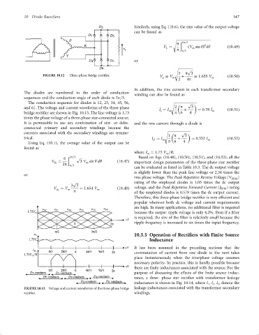
FIGURE 10.12 Three-phase bridge recti®er. V ¼ V þ ¼ 1:655 V ð10:50Þ
L
m
2 4p m
In addition, the rms current in each transformer secondary
The diodes are numbered in the order of conduction
winding can also be found as
sequences and the conduction angle of each diode is 2p=3.
The conduction sequence for diodes is 12, 23, 34, 45, 56, s
p
and 61. The voltage and current waveforms of the three-phase 2 p 3
I ¼ I m þ ¼ 0:78 I m ð10:51Þ
s
bridge recti®er are shown in Fig. 10.13. The line voltage is 1.73 p 6 4
times the phase voltage of a three-phase star-connected source.
It is permissible to use any combination of star- or delta- and the rms current through a diode is
connected primary and secondary windings because the
p
currents associated with the secondary windings are symme- s
1 p
trical. I ¼ I m þ 3 ¼ 0:552 I m ð10:52Þ
D
Using Eq. (10.1), the average value of the output can be p 6 4
found as
where I ¼ 1:73 V =R.
m
m
ð 2p=3 Based on Eqs. (10.48), (10.50), (10.51), and (10.52), all the
6 p
V ¼ 3 V sin y dy ð10:47Þ important design parameters of the three-phase star recti®er
m
dc
2p p=3
can be evaluated as listed in Table 10.3. The dc output voltage
is slightly lower than the peak line voltage or 2.34 times the
or
rms phase voltage. The Peak Repetitive Reverse Voltage (V )
RRM
p rating of the employed diodes is 1.05 times the dc output
3 3
V ¼ V ¼ 1:654 V ð10:48Þ voltage, and the Peak Repetitive Forward Current (I FRM ) rating
dc m p m of the employed diodes is 0.579 times the dc output current.
Therefore, this three-phase bridge recti®er is very ef®cient and
popular wherever both dc voltage and current requirements
are high. In many applications, no additional ®lter is required
because the output ripple voltage is only 4.2%. Even if a ®lter
is required, the size of the ®lter is relatively small because the
ripple frequency is increased to six times the input frequency.
10.3.3 Operation of Rectifiers with Finite Source
Inductance
It has been assumed in the preceding sections that the
commutation of current from one diode to the next takes
place instantaneously when the interphase voltage assumes
necessary polarity. In practice, this is hardly possible because
there are ®nite inductances associated with the source. For the
purpose of discussing the effects of the ®nite source induc-
tance, a three- phase star recti®er with transformer leakage
inductances is shown in Fig. 10.14, where l , l , l , denote the
2
3
1
FIGURE 10.13 Voltage and current waveforms of the three-phase bridge leakage inductances associated with the transformer secondary
recti®er. windings.