
Page 159 - Rashid, Power Electronics Handbook
P. 159
148 Y.-S. Lee and M. Chow
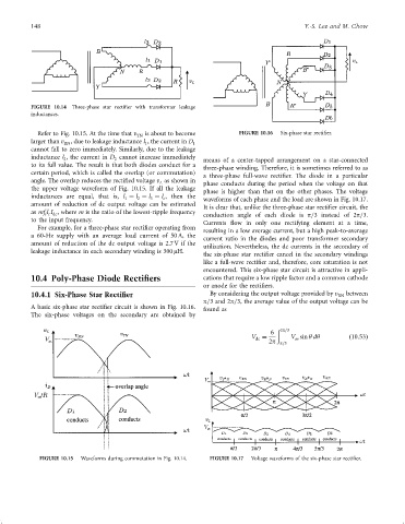
FIGURE 10.14 Three-phase star recti®er with transformer leakage
inductances.
Refer to Fig. 10.15. At the time that v is about to become FIGURE 10.16 Six-phase star recti®er.
YN
larger than v , due to leakage inductance l , the current in D
RN 1 1
cannot fall to zero immediately. Similarly, due to the leakage
inductance l , the current in D cannot increase immediately means of a center-tapped arrangement on a star-connected
2
2
to its full value. The result is that both diodes conduct for a
three-phase winding. Therefore, it is sometimes referred to as
certain period, which is called the overlap (or commutation)
a three-phase full-wave recti®er. The diode in a particular
angle. The overlap reduces the recti®ed voltage v as shown in phase conducts during the period when the voltage on that
L
the upper voltage waveform of Fig. 10.15. If all the leakage phase is higher than that on the other phases. The voltage
inductances are equal, that is, l ¼ l ¼ l ¼ l , then the waveforms of each phase and the load are shown in Fig. 10.17.
3
c
1
2
amount of reduction of dc output voltage can be estimated
It is clear that, unlike the three-phase star recti®er circuit, the
as mf l I , where m is the ratio of the lowest-ripple frequency conduction angle of each diode is p=3 instead of 2p=3.
i c dc
to the input frequency.
Currents ¯ow in only one rectifying element at a time,
For example, for a three-phase star recti®er operating from
resulting in a low average current, but a high peak-to-average
a 60-Hz supply with an average load current of 50 A, the
current ratio in the diodes and poor transformer secondary
amount of reduction of the dc output voltage is 2.7 V if the
utilization. Nevertheless, the dc currents in the secondary of
leakage inductance in each secondary winding is 300 mH.
the six-phase star recti®er cancel in the secondary windings
like a full-wave recti®er and, therefore, core saturation is not
encountered. This six-phase star circuit is attractive in appli-
10.4 Poly-Phase Diode Rectifiers cations that require a low ripple factor and a common cathode
or anode for the recti®ers.
10.4.1 Six-Phase Star Rectifier By considering the output voltage provided by v RN between
p=3 and 2p=3, the average value of the output voltage can be
A basic six-phase star recti®er circuit is shown in Fig. 10.16.
found as
The six-phase voltages on the secondary are obtained by
ð 2p=3
6
V ¼ V sin y dy ð10:53Þ
m
dc
2p p=3
FIGURE 10.15 Waveforms during commutation in Fig. 10.14. FIGURE 10.17 Voltage waveforms of the six-phase star recti®er.