
Page 178 - Rashid, Power Electronics Handbook
P. 178
10 Diode Recti®ers 167
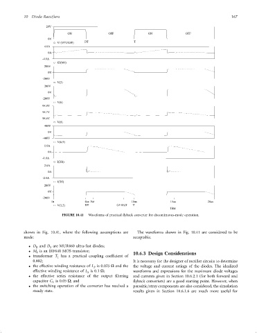
FIGURE 10.41 Waveforms of practical ¯yback converter for discontinuous-mode operation.
shown in Fig. 10.41, where the following assumptions are The waveforms shown in Fig. 10.41 are considered to be
made: acceptable.
D and D are MUR460 ultra-fast diodes;
R S
M is an IRF640 MOS transistor;
1 10.6.3 Design Considerations
transformer T has a practical coupling coef®cient of
1
0.992; It is necessary for the designer of recti®er circuits to determine
the effective winding resistance of L is 0:025 O and the the voltage and current ratings of the diodes. The idealized
P
effective winding resistance of L is 0:1 O; waveforms and expressions for the maximum diode voltages
S
the effective series resistance of the output ®ltering and currents given in Section 10.6.2.1 (for both forward and
capacitor C is 0:05 O; and ¯yback converters) are a good starting point. However, when
L
the switching operation of the converter has reached a parasitic=stray components are also considered, the simulation
steady state. results given in Section 10.6.1.6 are much more useful for