
Page 183 - Rashid, Power Electronics Handbook
P. 183
172 J. Rodrõ Âguez and A. Weinstein
input current can be expressed as a Fourier series, where the 11.1.5 Power Factor of the Rectifier
amplitude of the different harmonics is given by
The displacement factor of the fundamental current, obtained
from Fig. 11.8a, is
4 I d
I s max n ¼ ðn ¼ 1; 3; 5; ...Þ ð11:7Þ
p n cos f ¼ cos a ð11:12Þ
1
where n is the harmonic order. The root mean square (rms) In the case of nonsinusoidal current, the active power deliv-
value of each harmonic can be expressed as ered by the sinusoidal single-phase supply is
p ð
I s max n 2 2 I d 1 T
I ¼ p ¼ ð11:8Þ P ¼ v ðtÞi ðtÞdt ¼ V I cos f 1 ð11:13Þ
s
s
s s1
sn
2 p n T 0
Thus, the rms value of the fundamental current i is where V is the rms value of the single-phase voltage v .
s
s
s1
The apparent power is given by
p
2 2
I ¼ I ¼ 0:9I d ð11:9Þ S ¼ V I ð11:14Þ
s s
s1
d
p
The power factor (PF) is de®ned by
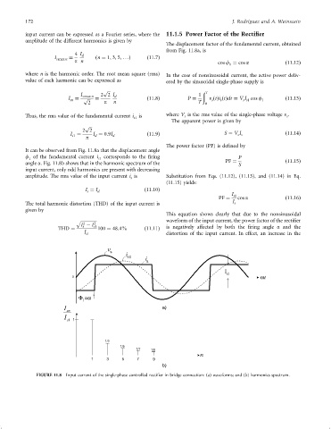
It can be observed from Fig. 11.8a that the displacement angle
f of the fundamental current i s1 corresponds to the ®ring P
1
angle a. Fig. 11.8b shows that in the harmonic spectrum of the PF ¼ S ð11:15Þ
input current, only odd harmonics are present with decreasing
amplitude. The rms value of the input current i is Substitution from Eqs. (11.12), (11.13), and (11.14) in Eq.
s
(11.15) yields:
I ¼ I d ð11:10Þ
s
I s1
PF ¼ cos a ð11:16Þ
The total harmonic distortion (THD) of the input current is I s
given by
This equation shows clearly that due to the nonsinusoidal
waveform of the input current, the power factor of the recti®er
p
2
2
I ÿ I s1
s
THD ¼ 100 ¼ 48:4% ð11:11Þ is negatively affected by both the ®ring angle a and the
I s1 distortion of the input current. In effect, an increase in the
v
s
i
s1
i
s
I
d
0 wt
F =a
1
I a)
sn
I
1 s 1
1/3
1/5
1/7 1/9
n
1 3 5 7 9
b)
FIGURE 11.8 Input current of the single-phase controlled recti®er in bridge connection: (a) waveforms; and (b) harmonics spectrum.