Page 186 - Rashid, Power Electronics Handbook
P. 186

11  Single-Phase Controlled Recti®ers                                                               175

                                                         T~i
                                                           d            These aspects have a negative in¯uence on both power
                                                                      factor and power quality. In the last several years, the massive
                                 i
                          Rect I  d     Rect II                       use of single-phase power converters has increased the
                                                       Rect. I
                  ac        v                ac                       problems of power quality in electrical systems. In effect,
                             d                                    w
                                                        0         r
                                  w r                                 modern commercial buildings have 50% and even up to
                                                      Rect. II        90% of the demand originated by nonlinear loads, which are
                                                                      composed mainly of recti®ers [1]. Today it is not unusual to
                                                                      ®nd recti®ers with total harmonic distortion of the current
                                a)                        b)          THD > 40% originating severe overloads in conductors and
                                                                          i
                 FIGURE 11.13  Single-phase dual-converter drive: (a) connection; and  transformers.
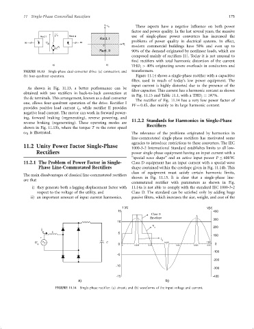
                 (b) four-quadrant operation.                           Figure 11.14 shows a single-phase recti®er with a capacitive
                                                                      ®lter, used in much of today's low power equipment. The
                                                                      input current is highly distorted due to the presence of the
                   As shown in Fig. 11.13, a better performance can be
                                                                      ®lter capacitor. This current has a harmonic content as shown
                 obtained with two recti®ers in back-to-back connection at
                                                                      in Fig. 11.15 and Table 11.1, with a THD ¼ 197%.
                                                                                                        i
                 the dc terminals. This arrangement, known as a dual converter
                                                                        The recti®er of Fig. 11.14 has a very low power factor of
                 one, allows four-quadrant operation of the drive. Recti®er I
                                                                      PF ¼ 0.45, due mainly to its large harmonic content.
                 provides positive load current i , while recti®er II provides
                                            d
                 negative load current. The motor can work in forward power-
                 ing, forward braking (regenerating), reverse powering, and  11.2.2 Standards for Harmonics in Single-Phase
                 reverse braking (regenerating). These operating modes are   Rectifiers
                 shown in Fig. 11.13b, where the torque T vs the rotor speed
                 o is illustrated.
                   R                                                  The relevance of the problems originated by harmonics in
                                                                      line-commutated single-phase recti®ers has motivated some
                                                                      agencies to introduce restrictions to these converters. The IEC
                 11.2 Unity Power Factor Single-Phase                 1000-3-2 International Standard establishes limits to all low-
                        Rectifiers                                     power single-phase equipment having an input current with a
                                                                      ‘‘special wave shape'' and an active input power P   600 W.
                 11.2.1 The Problem of Power Factor in Single-        Class D equipment has an input current with a special wave
                         Phase Line-Commutated Rectifiers              shape contained within the envelope given in Fig. 11.14b. This
                                                                      class of equipment must satisfy certain harmonic limits,
                 The main disadvantages of classical line-commutated recti®ers  shown in Fig. 11.15. It is clear that a single-phase line-
                 are that
                                                                      commutated recti®er with parameters as shown in Fig.
                      i) they generate both a lagging displacement factor with  11.14a is not able to comply with the standard IEC 1000-3-2
                        respect to the voltage of the utility, and    Class D. The standard can be satis®ed only by adding huge
                     ii) an important amount of input current harmonics.  passive ®lters, which increases the size, weight, and cost of the

                                                                  I [A]                                    V[V]
                                                               15                                             400
                                                                                Class D
                                                                               Envelope
                                                               10                                             300
                                                                                v s                           200
                          i
                           s   L
                                                                5                                             100
                                                                                    i
                          +                                                          s
                       v                                  C                           0,015                t [s]
                        s                                       0  0   0,005  0,01          0,02    0,025  0,03  0
                                                                                                              -100
                                                               -5
                                                                                                              -200
                                                              -10
                                                                                                              -300
                                                               -15                                            -400
                                            a)                                         b)
                                 FIGURE 11.14  Single-phase recti®er: (a) circuit; and (b) waveforms of the input voltage and current.
   181   182   183   184   185   186   187   188   189   190   191