
Page 191 - Rashid, Power Electronics Handbook
P. 191
180 J. Rodrõ Âguez and A. Weinstein
The waveform of the input current i can be controlled by Rectifier PFC Output Stage
s
appropriately switching transistors T -T or T -T , creating a EMI Lamp
2
4
1
3
shape similar to the one shown in Fig. 11.17a for the single- Line FILTER MC 33262 +
phase boost recti®er.
The control strategy for the recti®er is similar to the one
Dimming
depicted in Fig. 11.22 for the voltage doubler topology. The Control
quality of the input current obtained with this recti®er is the
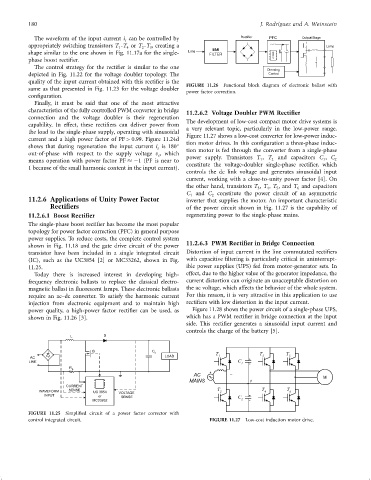
FIGURE 11.26 Functional block diagram of electronic ballast with
same as that presented in Fig. 11.23 for the voltage doubler power factor correction.
con®guration.
Finally, it must be said that one of the most attractive
characteristics of the fully controlled PWM converter in bridge 11.2.6.2 Voltage Doubler PWM Rectifier
connection and the voltage doubler is their regeneration
The development of low-cost compact motor drive systems is
capability. In effect, these recti®ers can deliver power from
a very relevant topic, particularly in the low-power range.
the load to the single-phase supply, operating with sinusoidal
Figure 11.27 shows a low-cost converter for low-power induc-
current and a high power factor of PF > 0.99. Figure 11.24d
shows that during regeneration the input current i is 180 tion motor drives. In this con®guration a three-phase induc-
s tion motor is fed through the converter from a single-phase
out-of-phase with respect to the supply voltage v , which
s
1
1
means operation with power factor PF ÿ1 (PF is near to power supply. Transistors T , T 2 and capacitors C , C 2
constitute the voltage-doubler single-phase recti®er, which
1 because of the small harmonic content in the input current).
controls the dc link voltage and generates sinusoidal input
current, working with a close-to-unity power factor [4]. On
the other hand, transistors T , T , T , and T and capacitors
3 4 5 6
C and C constitute the power circuit of an asymmetric
2
1
11.2.6 Applications of Unity Power Factor inverter that supplies the motor. An important characteristic
Rectifiers of the power circuit shown in Fig. 11.27 is the capability of
11.2.6.1 Boost Rectifier regenerating power to the single-phase mains.
The single-phase boost recti®er has become the most popular
topology for power factor correction (PFC) in general purpose
power supplies. To reduce costs, the complete control system
shown in Fig. 11.18 and the gate drive circuit of the power 11.2.6.3 PWM Rectifier in Bridge Connection
transistor have been included in a single integrated circuit Distortion of input current in the line commutated recti®ers
(IC), such as the UC3854 [2] or MC33262, shown in Fig. with capacitive ®ltering is particularly critical in uninterrupt-
11.25. ible power supplies (UPS) fed from motor-generator sets. In
Today there is increased interest in developing high- effect, due to the higher value of the generator impedance, the
frequency electronic ballasts to replace the classical electro- current distortion can originate an unacceptable distortion on
magnetic ballast in ¯uorescent lamps. These electronic ballasts the ac voltage, which affects the behavior of the whole system.
require an ac–dc converter. To satisfy the harmonic current For this reason, it is very attractive in this application to use
injection from electronic equipment and to maintain high recti®ers with low distortion in the input current.
power quality, a high-power factor recti®er can be used, as Figure 11.28 shows the power circuit of a single-phase UPS,
shown in Fig. 11.26 [3]. which has a PWM recti®er in bridge connection at the input
side. This recti®er generates a sinusoidal input current and
controls the charge of the battery [5].
L D
Q C o T T T
AC LOAD 1 + 3 5
LINE C
1 -
R S
+
AC
M
MAINS 0
CURRENT
WAVEFORM SENSE UC 3854 VOLTAGE T 2 T 4 T 6
INPUT or SENSE C +
MC33262 2 -
FIGURE 11.25 Simpli®ed circuit of a power factor corrector with
control integrated circuit. FIGURE 11.27 Low-cost induction motor drive.