
Page 195 - Rashid, Power Electronics Handbook
P. 195
184 J. W. Dixon
Power Transformer
Power Supply v D i D
v A i a
i A
i b
v B i B
v D i D
FIGURE 12.1 Three-phase half-wave recti®er.
a
V D
w
FIGURE 12.2 Instantaneous dc voltage n D , average dc voltage V D , and
®ring angle a.
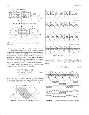
The ac currents of the half-wave recti®er are shown in Fig.
12.5. This drawing assumes that the dc current is constant
(very large L ). Disregarding commutation overlap, each valve
D
conducts during 120 per period. The secondary currents (and
thyristor currents) present a dc component that is undesirable, FIGURE 12.4 DC current waveforms.
and makes this recti®er not useful for high power applications.
The primary currents show the same waveform, but with the
transfer is with a ¼ 0 (or a ¼ 180 ). Then, to establish a
dc component removed. This very distorted waveform
relation between ac and dc voltages, Eq. (12.1) for a ¼ 0 is
requires an input ®lter to reduce harmonics contamination.
required:
The current waveforms shown in Fig. 12.5 are useful for
designing the power transformer. Starting from rms
V ¼ 1:17 V ðsecÞf ÿN ð12:3Þ
D
rms
rms
VA prim ¼ 3 V ðprimÞf ÿN I prim
rms
rms
VA sec ¼ 3 V ðsecÞf ÿN I sec ð12:2Þ
P ¼ V I
D D D
where VA and VA are the ratings of the transformer for
prim sec
the primary and secondary side, respectively. Here P is the
D
power transferred to the dc side. The maximum power
range of
w
FIGURE 12.3 Possible range for gating delay in angle a. FIGURE 12.5 AC current waveforms for the half-wave recti®er.