Page 200 - Rashid, Power Electronics Handbook
P. 200

12  Three-Phase Controlled Recti®ers                                                                189

                 Constant ‘‘C'' is evaluated through initial conditions at the  The area DV med  showed in Fig. 12.17 represents the loss of
                 instant when T2 is ignited. In terms of angle, when ot ¼ a:  voltage that affects the average voltage V , and can be
                                                                                                           C
                                                                      evaluated through the integration of Dn during the overlap
                                             sec
                                            V f ÿf
                          i ¼ 0    ; C ¼ p     cos a       ð12:18Þ  angle m. The voltage drop Dn can be expressed as
                          sc
                                            2   oL S
                                                                                              p  
                                                                                     n ÿ n     2   V sec  sin ot
                 Replacing Eq. (12.18) in Eq. (12.17):                        Dn ¼   A   B  ¼      f ÿf            ð12:21Þ
                                                                                      2             2
                                    V f ÿf
                              i ¼ p     ðcos a ÿ cos otÞ   ð12:19Þ
                              sc
                                    2   oL S                          Integrating Eq. (12.21) into the corresponding period (60 )
                                                                      and interval (m), at the instant when the commutation begins
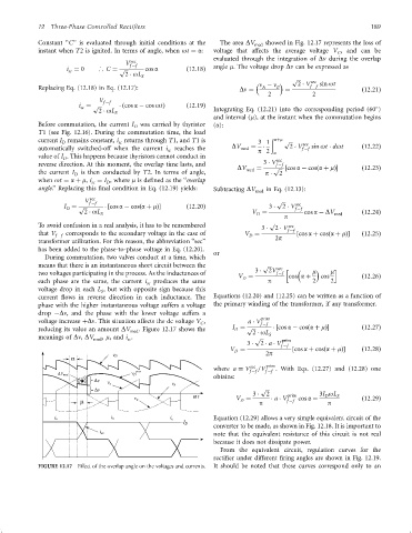
                 Before commutation, the current I was carried by thyristor  (a):
                                              D
                 T1 (see Fig. 12.16). During the commutation time, the load
                 current I remains constant, i returns through T1, and T1is        3 1  ð aþm  p   sec
                         D
                                          sc

                 automatically switched-off when the current i sc  reaches the  DV med  ¼  p 2  a  2   V f ÿf  sin ot   dot  ð12:22Þ
                 value of I . This happens because thyristors cannot conduct in          sec
                         D
                 reverse direction. At this moment, the overlap time lasts, and      3   V f ÿf
                                                                             DV med  ¼  p  ‰cos a ÿ cosða þ mފ  ð12:23Þ
                 the current I D  is then conducted by T2. In terms of angle,         p    2
                 when ot ¼ a þ m, i ¼ I , where m is de®ned as the ‘‘overlap
                                 sc
                                      D
                 angle.'' Replacing this ®nal condition in Eq. (12.19) yields:  Subtracting DV med  in Eq. (12.13):
                                 sec
                               V f ÿf                                                    p 
                                                                                               sec
                         I ¼ p     ‰cos a ÿ cosða þ mފ    ð12:20Þ                  3    2   V f ÿf
                          D
                               2   oL S                                           V ¼      p     cos a ÿ DV med    ð12:24Þ
                                                                                   D
                                                                                       p
                 To avoid confusion in a real analysis, it has to be remembered            sec
                                                                                    3    2   V f ÿf
                 that V   corresponds to the secondary voltage in the case of  V ¼             ‰cos a þ cosða þ mފ  ð12:25Þ
                       f ÿf                                                      D       2p
                 transformer utilization. For this reason, the abbreviation ‘‘sec''
                 has been added to the phase-to-phase voltage in Eq. (12.20).
                                                                      or
                   During commutation, two valves conduct at a time, which
                 means that there is an instantaneous short circuit between the      p 
                                                                                   3    2V  sec h     m    m i
                 two voltages participating in the process. As the inductances of        f ÿf
                                                                             V ¼             cos a þ  cos          ð12:26Þ
                                                                               D
                 each phase are the same, the current i sc  produces the same         p             2    2
                 voltage drop in each L , but with opposite sign because this
                                    S
                 current ¯ows in reverse direction in each inductance. The  Equations (12.20) and (12.25) can be written as a function of
                 phase with the higher instantaneous voltage suffers a voltage  the primary winding of the transformer, if any transformer.
                 drop ÿDn, and the phase with the lower voltage suffers a
                                                                                    prim
                 voltage increase þDn. This situation affects the dc voltage V ,  a   V f ÿf
                                                                  C
                 reducing its value an amount DV med . Figure 12.17 shows the  I ¼ p    ‰cos a ÿ cosða þ mފ    ð12:27Þ
                                                                            D
                                                                                  2   oL
                 meanings of Dn, DV med , m, and i .                              p   S  prim
                                            sc
                                                                                3    2   a   V f ÿf
                                                                           V ¼                ‰cos a þ cosða þ mފ  ð12:28Þ
                                                                            D         2p
                                        v D
                           a
                                                                      where a ¼ V sec  =V prim . With Eqs. (12.27) and (12.28) one
                                                                                 f ÿf  f ÿf
                       DV med
                                                                      obtains:
                                  Dv
                                      v c
                                  Dv                                                p 
                                                                w            V ¼  3    2    a   V prim  cos a ÿ  3I oL S  ð12:29Þ
                                                                                                       D
                              m                                               D     p       f ÿf        p
                                                                      Equation (12.29) allows a very simple equivalent circuit of the
                                                                      converter to be made, as shown in Fig. 12.18. It is important to
                                                                      note that the equivalent resistance of this circuit is not real
                                                                      because it does not dissipate power.
                                                                        From the equivalent circuit, regulation curves for the
                                                                      recti®er under different ®ring angles are shown in Fig. 12.19.
                 FIGURE 12.17  Effect of the overlap angle on the voltages and currents.  It should be noted that these curves correspond only to an
   195   196   197   198   199   200   201   202   203   204   205