
Page 201 - Rashid, Power Electronics Handbook
P. 201
190 J. W. Dixon
3 where V a rms is the rms value of the voltage n , and I a1 the rms
rms
a
value of i a1 (fundamental component of i ). Analog relations
a
can be obtained for n and n .
b
c
The apparent power per phase is given by
I
S ¼ V a rms rms ð12:32Þ
a
FIGURE 12.18 Equivalent circuit for the converter.
The power factor is de®ned by
P
PF ¼ ð12:33Þ
S
V D
/ a
(3Ö2p)V f-f By substituting Eqs. (12.30), (12.31) and (12.32) into Eq.
/ a (12.33), the power factor can be expressed as follows
(3Ö2p)V f-f cosa 1
rms
I a1
PF ¼ cos a ð12:34Þ
I a rms
This equation shows clearly that due to the nonsinusoidal
waveform of the currents, the power factor of the recti®er is
negatively affected by both the ®ring angle a and the distortion
FIGURE 12.19 Direct current voltage regulation curves for recti®er of the input current. In effect, an increase in the distortion
operation. rms
of the current produces an increase in the value of I in
a
Eq. (12.34), which deteriorates the power factor.
i 12.2.8 Harmonic Distortion
The currents of the line-commutated recti®ers are far from
being sinusoidal. For example, the currents generated from the
a m Graetz recti®er (see Fig. 12.14b) have the following harmonic
v a
content:
p
2 3 1 1
i ¼ I cos ot ÿ cos 5ot þ cos 7ot
A p D 5 7
1
ÿ cos 11ot þ ð12:35Þ
11
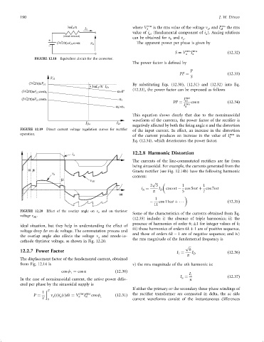
FIGURE 12.20 Effect of the overlap angle on n a and on thyristor
Some of the characteristics of the currents obtained from Eq.
voltage n AK .
(12.35) include: i) the absence of triple harmonics; ii) the
presence of harmonics of order 6; 1 for integer values of k;
ideal situation, but they help in understanding the effect of
iii) those harmonics of orders 6k þ 1 are of positive sequence,
voltage drop Dn on dc voltage. The commutation process and
and those of orders 6k ÿ 1 are of negative sequence; and iv)
the overlap angle also affects the voltage n and anode-to-
a
cathode thyristor voltage, as shown in Fig. 12.20. the rms magnitude of the fundamental frequency is
p
12.2.7 Power Factor I ¼ 6 I ð12:36Þ
1
p D
The displacement factor of the fundamental current, obtained
from Fig. 12.14 is v) the rms magnitude of the nth harmonic is:
cos f ¼ cos a ð12:30Þ
1 I
I ¼ 1 ð12:37Þ
In the case of nonsinusoidal current, the active power deliv- n n
ered per phase by the sinusoidal supply is
If either the primary or the secondary three-phase windings of
ð T
1 rms rms
P ¼ n ðtÞi ðtÞdt ¼ V a I a1 cos f 1 ð12:31Þ the recti®er transformer are connected in delta, the ac side
a
a
T 0 current waveforms consist of the instantaneous differences