
Page 202 - Rashid, Power Electronics Handbook
P. 202
12 Three-Phase Controlled Recti®ers 191
between two rectangular secondary currents 120 apart as two Fourier series of the star connection (Eq. 12.35) and delta
shown in Fig. 12.14e). The resulting Fourier series for the connection transformers (Eq. 12.38):
current in phase ‘‘a'' on the primary side is
p
2 3 1 1
p i ¼ 2 I cos ot ÿ cos 11ot þ cos 13ot
2 3 1 1 A p D 11 13
i ¼ I D cos ot þ cos 5ot ÿ cos 7ot
A
p 5 7 1
ÿ cos 23t þ ð12:39Þ
1 23
ÿ cos 11ot þ ð12:38Þ
11
The series contains only harmonics of order 12k 1. The
This series differs from that of a star-connected transformer harmonic currents of orders 6k 1 (with k odd), that is, 5th,
only by the sequence of rotation of harmonic orders 6k 1 for 7th, 17th, 19th, etc., circulate between the two converter
odd values of k, that is, 5th, 7th, 17th, 19th, etc. transformers but do not penetrate the ac network.
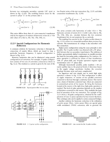
The resulting line current for the 12-pulse recti®er shown in
Fig. 12.23 is closer to a sinusoidal waveform than previous line
12.2.9 Special Configurations for Harmonic currents. The instantaneous dc voltage is also smoother with
Reduction this connection.
Higher pulse con®guration using the same principle is also
A common solution for harmonic reduction is through the possible. The 12-pulse recti®er was obtained with a 30 phase-
connection of passive ®lters, which are tuned to trap a shift between the two secondary transformers. The addition of
particular harmonic frequency. A typical con®guration is
further appropriately shifted transformers in parallel provides
shown in Fig. 12.21.
the basis for increasing pulse con®gurations. For instance, 24-
However, harmonics also can be eliminated using special
pulse operation is achieved by means of four transformers
con®gurations of converters. For example, 12-pulse con®gura-
with 15 phase-shift, and 48-pulse operation requires eight
tion consists of two sets of converters connected as shown in
transformers with 7:5 phase-shift.
Fig. 12.22. The resultant ac current is given by the sum of the
Although theoretically possible, pulse numbers >48 are
rarely justi®ed due to the practical levels of distortion found
in the supply voltage waveforms. Further, the converter
topology becomes more and more complicated.
An ingenious and very simple way to reach high pulse
operation is shown in Fig. 12.24. This con®guration is called
dc ripple reinjection. It consists of two parallel converters
connected to the load through a multistep reactor. The reactor
uses a chain of thyristor-controlled taps, which are connected
to symmetrical points of the reactor. By ®ring the thyristors
located at the reactor at the right time, high-pulse operation is
FIGURE 12.21 Typical passive ®lter for one phase.
reached. The level of pulse operation depends on the number
of thyristors connected to the reactor. They multiply the basic
level of operation of the two converters. The example of Fig.
12.24 shows a 48-pulse con®guration, obtained by the multi-
plication of basic 12-pulse operation by four reactor thyristors.
This technique also can be applied to series connected bridges.
Y D
i A Y Another solution for harmonic reduction is the utilization
v A i a i a
of active power ®lters. Active power ®lters are special pulse
Y D
width modulated (PWM) converters, able to generate the
i B i b i b
i A
FIGURE 12.22 A 12-pulse recti®er con®guration. FIGURE 12.23 Line current for the 12-pulse recti®er.