
Page 203 - Rashid, Power Electronics Handbook
P. 203
192 J. W. Dixon
rants Ð positive and negative dc voltage. This two-quadrant
Y operation allows regenerative braking when a > 90 , and
I exc < 0.
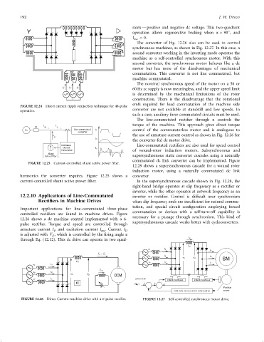
The converter of Fig. 12.26 also can be used to control
synchronous machines, as shown in Fig. 12.27. In this case, a
second converter working in the inverting mode operates the
machine as a self-controlled synchronous motor. With this
second converter, the synchronous motor behaves like a dc
motor but has none of the disadvantages of mechanical
commutation. This converter is not line commutated, but
machine commutated.
The nominal synchronous speed of the motor on a 50 or
60 Hz ac supply is now meaningless, and the upper speed limit
is determined by the mechanical limitations of the rotor
construction. There is the disadvantage that the rotational
emfs required for load commutation of the machine side
FIGURE 12.24 Direct current ripple reinjection technique for 48-pulse
converter are not available at standstill and low speeds. In
operation.
such a case, auxiliary force commutated circuits must be used.
The line-commutated recti®er through a controls the
jX I S I L torque of the machine. This approach gives direct torque
Vs control of the commutatorless motor and is analogous to
I the use of armature current control as shown in Fig. 12.26 for
F
the converter-fed dc motor drive.
Line-commutated recti®ers are also used for speed control
of wound-rotor induction motors. Subsynchronous and
supersynchronous static converter cascades using a naturally
commutated dc link converter can be implemented. Figure
FIGURE 12.25 Current-controlled shunt active power ®lter.
12.28 shows a supersynchronous cascade for a wound rotor
induction motor, using a naturally commutated dc link
harmonics the converter requires. Figure 12.25 shows a converter.
current-controlled shunt active power ®lter. In the supersynchronous cascade shown in Fig. 12.28, the
right-hand bridge operates at slip frequency as a recti®er or
inverter, while the other operates at network frequency as an
12.2.10 Applications of Line-Commutated inverter or recti®er. Control is dif®cult near synchronism
Rectifiers in Machine Drives when slip frequency emfs are insuf®cient for natural commu-
tation, and special circuit con®guration employing forced
Important applications for line-commutated three-phase
commutation or devices with a self-turn-off capability is
controlled recti®ers are found in machine drives. Figure
necessary for a passage through synchronism. This kind of
12.26 shows a dc machine control implemented with a 6-
supersynchronous cascade works better with cycloconverters.
pulse recti®er. Torque and speed are controlled through
armature current I D and excitation current I . Current I D
exc
is adjusted with V , which is controlled by the ®ring angle a
D
through Eq. (12.12). This dc drive can operate in two quad-
v A i A
v B i B
v D
v C i C
v A i A
FIGURE 12.26 Direct Current machine drive with a 6-pulse recti®er. FIGURE 12.27 Self-controlled synchronous motor drive.