
Page 207 - Rashid, Power Electronics Handbook
P. 207
196 J. W. Dixon
TABLE 12.1 Harmonic current limits in percent of fundamental
Short circuit current [pu] h < 11 11 < h < 17 17 < h < 23 23 < h < 35 35 < h THD
<20 4.0 2.0 1.5 0.6 0.3 5.0
20–50 7.0 3.5 2.5 1.0 0.5 8.0
50–100 10.0 4.5 4.0 1.5 0.7 12.0
100–1000 12.0 5.5 5.0 2.0 1.0 15.0
>1000 15.0 7.0 6.0 2.5 1.4 20.0
current injection to maintain good power quality. As a TABLE 12.2 Harmonic voltage limits in percent of fundamental
consequence, various standards and guidelines have been
Voltage Level 2:3–6:9 kV 69–138 kV >138 kV
established that specify limits on the magnitudes of harmonic
currents and harmonic voltages. Maximum for individual 3.0 1.5 1.0
The Comite  Europe Âen de Normalisation Electrotechnique harmonic
Total Harmonic Distortion 5.0 2.5 1.5
(CENELEC), International Electrical Commission (IEC), and
(THD)
West German Standards (VDE) specify the limits on the
voltages (as a percentage of the nominal voltage) at various
harmonics frequencies of the utility frequency, when the which is not possible with line-commutated recti®ers, where
equipment-generated harmonic currents are injected into a thyristors are switched ON and OFF only once a cycle. This
network whose impedances are speci®ed. feature confers the following advantages: (a) the current or
In accordance with IEEE-519 standards (Institute of Elec- voltage can be modulated (pulse width modulation or PWM),
trical and Electronic Engineers), Table 12.1 lists the limits on generating less harmonic contamination; (b) the power factor
the harmonic currents that a user of power electronics equip- can be controlled, and it can even be made to lead; (c) recti®ers
ment and other nonlinear loads is allowed to inject into the canbebuiltasvoltageorcurrentsourcetypes;and(d)thereversal
utility system. Table 12.2 lists the quality of voltage that the of power in thyristor recti®ers is by reversal of voltage
utility can furnish the user. at the dc link. By contrast, force-commutated recti®ers can be
In Table 12.1, the values are given at the point of connection implemented for either reversal of voltage or reversal of current.
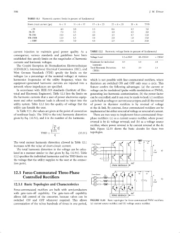
of nonlinear loads. The THD is the total harmonic distortion There are two ways to implement force-commutated three-
given by Eq. (12.51), and h is the number of the harmonic. phase recti®ers: (a) as a current source recti®er, where power
reversal is by dc voltage reversal; and (b) as a voltage source
s
1 recti®er, where power reversal is by current reversal at the dc
P 2
I h link. Figure 12.35 shows the basic circuits for these two
h¼2
THD ¼ ð12:51Þ topologies.
I
1
The total current harmonic distortion allowed in Table 12.1
Power Source
increases with the value of short-circuit current.
The total harmonic distortion in the voltage can be calcu-
lated in a manner similar to that given by Eq. (12.51). Table
12.2 speci®es the individual harmonics and the THD limits on
the voltage that the utility supplies to the user at the connec- C S
tion point.
PWM SIGNALS
12.3 Force-Commutated Three-Phase
Controlled Rectifiers
12.3.1 Basic Topologies and Characteristics
Force-commutated recti®ers are built with semiconductors
with gate-turn-off capability. The gate-turn-off capability
allows full control of the converter, because valves can be
switched ON and OFF whenever required. This allows FIGURE 12.35 Basic topologies for force-commutated PWM recti®ers:
commutation of the valves hundreds of times in one period, (a) current source recti®er; and (b) voltage source recti®er.