
Page 210 - Rashid, Power Electronics Handbook
P. 210
12 Three-Phase Controlled Recti®ers 199
v = V M sin wt
A
L S A R
i s
B
v B i s
C
C
v i s
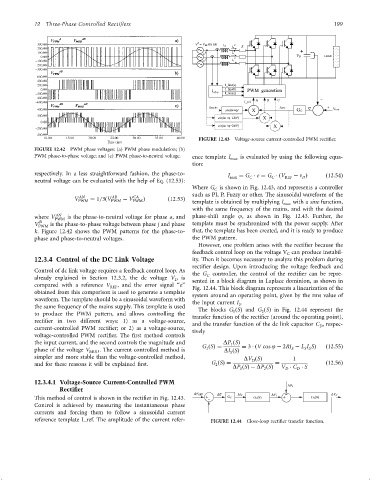
FIGURE 12.43 Voltage-source current-controlled PWM recti®er.
FIGURE 12.42 PWM phase voltages: (a) PWM phase modulation; (b)
PWM phase-to-phase voltage; and (c) PWM phase-to-neutral voltage. ence template I max is evaluated by using the following equa-
tion:
respectively. In a less straightforward fashion, the phase-to- I max ¼ G e ¼ G ðV REF ÿ n Þ ð12:54Þ
C
C
D
neutral voltage can be evaluated with the help of Eq. (12.53):
Where G is shown in Fig. 12.43, and represents a controller
C
such as PI, P, Fuzzy or other. The sinusoidal waveform of the
AB
CA
AN
V PWM ¼ 1=3ðV PWM ÿ V PWM Þ ð12:53Þ
template is obtained by multiplying I
max with a sine function,
with the same frequency of the mains, and with the desired
AN
where V PWM is the phase-to-neutral voltage for phase a, and phase-shift angle j, as shown in Fig. 12.43. Further, the
jk
V PWM is the phase-to-phase voltage between phase j and phase template must be synchronized with the power supply. After
k. Figure 12.42 shows the PWM patterns for the phase-to- that, the template has been created, and it is ready to produce
phase and phase-to-neutral voltages. the PWM pattern.
However, one problem arises with the recti®er because the
feedback control loop on the voltage V C can produce instabil-
12.3.4 Control of the DC Link Voltage ity. Then it becomes necessary to analyze this problem during
recti®er design. Upon introducing the voltage feedback and
Control of dc link voltage requires a feedback control loop. As
the G controller, the control of the recti®er can be repre-
C
already explained in Section 12.3.2, the dc voltage V D is sented in a block diagram in Laplace dominion, as shown in
compared with a reference V REF , and the error signal ‘‘e'' Fig. 12.44. This block diagram represents a linearization of the
obtained from this comparison is used to generate a template
system around an operating point, given by the rms value of
waveform. The template should be a sinusoidal waveform with
the input current I .
S
the same frequency of the mains supply. This template is used
The blocks G ðSÞ and G ðSÞ in Fig. 12.44 represent the
1
2
to produce the PWM pattern, and allows controlling the transfer function of the recti®er (around the operating point),
recti®er in two different ways: 1) as a voltage-source, and the transfer function of the dc link capacitor C , respec-
current-controlled PWM recti®er; or 2) as a voltage-source, tively D
voltage-controlled PWM recti®er. The ®rst method controls
the input current, and the second controls the magnitude and DP ðSÞ
1
G ðSÞ¼ ¼ 3 ðV cos j ÿ 2RI ÿ L I SÞ ð12:55Þ
1
S S
S
phase of the voltage V . The current controlled method is
MOD DI ðSÞ
S
simpler and more stable than the voltage-controlled method, DV ðSÞ 1
D
and for these reasons it will be explained ®rst. G ðSÞ¼ ¼ ð12:56Þ
2
DP ðSÞÿ DP ðSÞ V C S
2
D
1
D
12.3.4.1 Voltage-Source Current-Controlled PWM
Rectifier
DV REF DE DI S
This method of control is shown in the recti®er in Fig. 12.43. G
Control is achieved by measuring the instantaneous phase
currents and forcing them to follow a sinusoidal current
reference template I_ref. The amplitude of the current refer- FIGURE 12.44 Close-loop recti®er transfer function.