
Page 214 - Rashid, Power Electronics Handbook
P. 214
12 Three-Phase Controlled Recti®ers 203
In this method, there are two important parameters to
de®ne: the amplitude modulation ratio, or modulation index
m, and the frequency modulation ratio p. De®nitions are given
by
V MOD max
m ¼ ð12:68Þ
V TRIANG max
f T
p ¼ ð12:69Þ
f S
Where V max and V max are the amplitudes of V and
MOD TRIANG MOD
V , respectively. On the other hand, f is the frequency of
TRIANG S
the mains supply and f the frequency of the triangular carrier.
T
In Fig. 12.51, m ¼ 0:8 and p ¼ 21. When m > 1 overmodula-
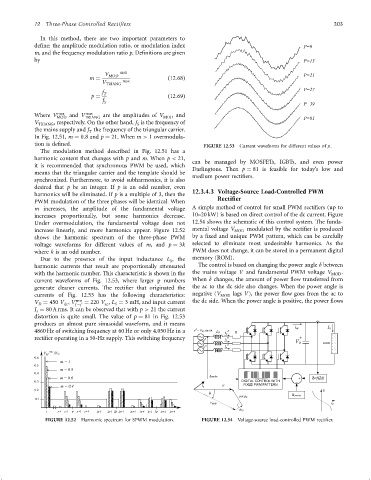
tion is de®ned. FIGURE 12.53 Current waveforms for different values of p.
The modulation method described in Fig. 12.51 has a
harmonic content that changes with p and m. When p < 21,
can be managed by MOSFETs, IGBTs, and even power
it is recommended that synchronous PWM be used, which
Darlingtons. Then p ¼ 81 is feasible for today's low and
means that the triangular carrier and the template should be
medium power recti®ers.
synchronized. Furthermore, to avoid subharmonics, it is also
desired that p be an integer. If p is an odd number, even
harmonics will be eliminated. If p is a multiple of 3, then the 12.3.4.3 Voltage-Source Load-Controlled PWM
PWM modulation of the three phases will be identical. When Rectifier
m increases, the amplitude of the fundamental voltage A simple method of control for small PWM recti®ers (up to
increases proportionally, but some harmonics decrease. 10–20 kW) is based on direct control of the dc current. Figure
Under overmodulation, the fundamental voltage does not 12.54 shows the schematic of this control system. The funda-
increase linearly, and more harmonics appear. Figure 12.52 mental voltage V MOD modulated by the recti®er is produced
shows the harmonic spectrum of the three-phase PWM by a ®xed and unique PWM pattern, which can be carefully
voltage waveforms for different values of m, and p ¼ 3k selected to eliminate most undesirable harmonics. As the
where k is an odd number. PWM does not change, it can be stored in a permanent digital
Due to the presence of the input inductance L , the memory (ROM).
S
harmonic currents that result are proportionally attenuated The control is based on changing the power angle d between
with the harmonic number. This characteristic is shown in the the mains voltage V and fundamental PWM voltage V MOD .
current waveforms of Fig. 12.53, where larger p numbers When d changes, the amount of power ¯ow transferred from
generate cleaner currents. The recti®er that originated the the ac to the dc side also changes. When the power angle is
currents of Fig. 12.53 has the following characteristics: negative (V MOD lags V), the power ¯ow goes from the ac to
V ¼ 450 V ; V rms ¼ 220 V , L ¼ 3 mH, and input current the dc side. When the power angle is positive, the power ¯ows
D dc f ÿf ac S
I ¼ 80 A rms. It can be observed that with p > 21 the current
s
distortion is quite small. The value of p ¼ 81 in Fig. 12.53
produces an almost pure sinusoidal waveform, and it means
A
4860 Hz of switching frequency at 60 Hz or only 4.050 Hz in a v = V M sin wt L S A R
i s
recti®er operating in a 50-Hz supply. This switching frequency B
v B i s
C
C
v I s
0.6
m=1
0.5
m = 0.8
0.4
m = 0.6
0.3
w
FIGURE 12.52 Harmonic spectrum for SPWM modulation. FIGURE 12.54 Voltage-source load-controlled PWM recti®er.