
Page 218 - Rashid, Power Electronics Handbook
P. 218
12 Three-Phase Controlled Recti®ers 207
Figure 12.64 shows the voltage waveforms for different
number of converters connected in the bridge. It is clear
that the larger the number of converters, the better the voltage.
Another interesting result with this converter is that the ac
voltages become modulated by both pulsewidth and ampli-
Total current
tude (PWM and AM). This is because when the pulse
modulation changes, the steps of the amplitude change. The
maximum number of steps of the resultant voltage is equal to
the number of converters. When the voltage decreases, some
steps disappear, and then the amplitude modulation becomes
a discrete function. Figure 12.65 shows the amplitude modu-
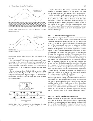
FIGURE 12.59 Input currents and carriers of the series connection lation of the voltage.
system of Fig. 12.58.
12.3.5.4 Machine Drives Applications
One of the most important applications of force-commutated
recti®ers is in machine drives. Line-commutated thyristor
converters have limited applications because they need excita-
tion to extinguish the valves. This limitation do not allow the
use of line-commutated converters in induction machine
drives. On the other hand, with force-commutated converters
four-quadrant operation is achievable. Figure 12.66 shows a
FIGURE 12.60 Four converters in series and p ¼ 9, compared with one
typical frequency converter with a force-commutated recti®er-
converter and p ¼ 36.
inverter link. The recti®er side controls the dc link, and the
inverter side controls the machine. The machine can be a
synchronous, brushless dc, or induction machine. The reversal
connected in parallel at the converter side, and in series at the
of both speed and power are possible with this topology. At
load side.
the recti®er side, the power factor can be controlled, and even
The system uses SPWM with triangular carriers shifted, and
with an inductive load such as an induction machine, the
depending on the number of converters connected in the
chain of bridges, the voltage waveform becomes more and source can ‘‘see'' the load as capacitive or resistive. Changing
more sinusoidal. Figure 12.62 shows a back-to-back system the frequency of the inverter controls the machine speed, and
the torque is controlled through the stator currents and torque
using a chain of 12 ‘‘H'' converters connected as shown in Fig.
angle. The inverter will become a recti®er during regenerative
12.61b.
braking, which is possible by making slip negative in an
The ac voltage waveform obtained with the topology of Fig.
12.62 is displayed in Fig. 12.63. It can be observed that the induction machine, or by making the torque angle negative
voltage is formed by small steps that depend on the number of in synchronous and brushless dc machines.
converters in the chain (12 in this case). The current is almost A variation of the drive of Fig. 12.66 is found in electric
traction applications. Battery-powered vehicles use the inver-
perfectly sinusoidal.
ter as a recti®er during regenerative braking, and sometimes
the inverter is also used as a battery charger. In this case, the
recti®er can be fed by a single-phase or by a three-phase
+ system. Figure 12.67 shows a battery-powered electric bus
system. This system uses the power inverter of the traction
motor as a recti®er for two purposes: regenerative braking;
and as a battery charger fed by a three-phase power source.
12.3.5.5 Variable Speed Power Generation
Power generation at 50 or 60 Hz requires constant speed
machines. In addition, induction machines are not currently
used in power plants because of magnetization problems. With
FIGURE 12.61 The ‘‘H'' modulator: (a) one bridge; and (b) bridge the use of frequency-link force-commutated converters, vari-
connected in series at load side through isolation transformers. able-speed constant-frequency generation becomes possible,