
Page 216 - Rashid, Power Electronics Handbook
P. 216
12 Three-Phase Controlled Recti®ers 205
I D L D
50 Hz
Y
D
D
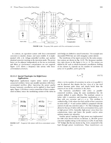
FIGURE 12.56 Frequency link systems with line-commutated converters.
In contrast, an equivalent system with force-commutated each bridge are shifted to cancel harmonics. The example uses
converters is simpler, cleaner, and more reliable. It is imple- sinusoidal PWM that are with triangular carrier shifted.
mented with a dc voltage-controlled recti®er, and another The waveforms of the input currents for the series connec-
identical converter working in the inversion mode. The power tion system are shown in Fig. 12.59. The frequency modula-
factor can be adjusted independently at the two ac terminals, tion ratio shown in this ®gure is for p ¼ 9. The carriers are
and ®lters or synchronous compensators are not required. shifted by 90 each to obtain harmonics cancellation. Shifting
Figure 12.57 shows a frequency link system with force- of the carriers d depends on the number of converters in
T
commutated converters. series (or in parallel), and is given by
2p
12.3.5.3 Special Topologies for High-Power d ¼ n ð12:71Þ
T
Applications
High-power applications require series- and=or parallel-
where n is the number of converters in series or in parallel. It
connected recti®ers. Series and parallel operation with force-
can be observed that despite the low value of p, the total
commutated recti®ers allow improving the power quality
current becomes quite clean, and clearly better than the
because harmonic cancellation can be applied to these topol-
current of one of the converters in the chain.
ogies. Figure 12.58 shows a series connection of force-commu-
The harmonic cancellation with series- or parallel-
tated recti®ers, where the modulating carriers of the valves in
connected recti®ers, using the same modulation but the
carriers shifted, is quite effective. The resultant current is
better with n converters and frequency modulation p ¼ p 1
than with one converter and p ¼ n p . This attribute is
1
50 Hz veri®ed in Fig. 12.60, where the total current of four converters
50 Hz V D in series with p ¼ 9 and carriers shifted is compared with the
PWM current of only one converter and p ¼ 36. This technique also
allows for the use of valves with slow commutation times, such
as high-power GTOs. Generally, high-power valves have low
commutation times and hence the parallel and=or series
options remain very attractive.
Another special topology for high power was implemented
for ABB (Asea Brown Boveri) in Bremen. A 100-MW power
2
converter supplies energy to the railways at 1 Hz. It uses basic
3
FIGURE 12.57 Frequency link systems with force-commutated conver- ‘‘H'' bridges like the one shown in Fig. 12.61, connected to the
ters. load through power transformers. These transformers are