
Page 219 - Rashid, Power Electronics Handbook
P. 219
208 J. W. Dixon
I D1
"H"
"H"
"H"
50 Hz "H"
"H"
phase "b" "H"
phase "c" "H"
"H"
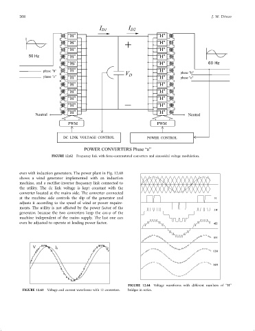
FIGURE 12.62 Frequency link with force-commutated converters and sinusoidal voltage modulation.
even with induction generators. The power plant in Fig. 12.68
shows a wind generator implemented with an induction
machine, and a recti®er-inverter frequency link connected to
the utility. The dc link voltage is kept constant with the
converter located at the mains side. The converter connected
at the machine side controls the slip of the generator and
adjusts it according to the speed of wind or power require-
ments. The utility is not affected by the power factor of the
generator, because the two converters keep the cos j of the
machine independent of the mains supply. The last one can
even be adjusted to operate at leading power factor.
V I S
FIGURE 12.64 Voltage waveforms with different numbers of ‘‘H''
FIGURE 12.63 Voltage and current waveforms with 12 converters. bridges in series.