
Page 215 - Rashid, Power Electronics Handbook
P. 215
204 J. W. Dixon
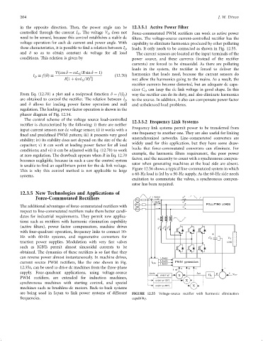
in the opposite direction. Then, the power angle can be 12.3.5.1 Active Power Filter
controlled through the current I . The voltage V does not Force-commutated PWM recti®ers can work as active power
D
D
need to be sensed, because this control establishes a stable dc ®lters. The voltage-source current-controlled recti®er has the
voltage operation for each dc current and power angle. With capability to eliminate harmonics produced by other polluting
these characteristics, it is possible to ®nd a relation between I D loads. It only needs to be connected as shown in Fig. 12.55.
and d so as to obtain constant dc voltage for all load The current sensors are located at the input terminals of the
conditions. This relation is given by power source, and these currents (instead of the recti®er
currents) are forced to be sinusoidal. As there are polluting
loads in the system, the recti®er is forced to deliver the
Vðcos d ÿ oL =R sin d ÿ 1Þ harmonics that loads need, because the current sensors do
S
I ¼ f ðdÞ¼ 2 ð12:70Þ
D
R1 þðoL =RÞ not allow the harmonics going to the mains. As a result, the
S
recti®er currents become distorted, but an adequate dc capa-
citor C can keep the dc link voltage in good shape. In this
D
From Eq. (12.70) a plot and a reciprocal function d ¼ f ðI Þ way the recti®er can do its duty, and also eliminate harmonics
D
are obtained to control the recti®er. The relation between I D to the source. In addition, it also can compensate power factor
and d allows for leading power factor operation and null and unbalanced load problems.
regulation. The leading power factor operation is shown in the
phasor diagram of Fig. 12.54.
The control scheme of the voltage source load-controlled 12.3.5.2 Frequency Link Systems
recti®er is characterized by the following: i) there are neither
Frequency link systems permit power to be transferred from
input current sensors nor dc voltage sensor; ii) it works with a
one frequency to another one. They are also useful for linking
®xed and prede®ned PWM pattern; iii) it presents very good
unsynchronized networks. Line-commutated converters are
stability; iv) its stability does not depend on the size of the dc
capacitor; v) it can work at leading power factor for all load widely used for this application, but they have some draw-
conditions; and vi) it can be adjusted with Eq. (12.70) to work backs that force-commutated converters can eliminate. For
at zero regulation. The drawback appears when R in Eq. 12.70 example, the harmonic ®lters requirement, the poor power
factor, and the necessity to count with a synchronous compen-
becomes negligible, because in such a case the control system
sator when generating machines at the load side are absent.
is unable to ®nd an equilibrium point for the dc link voltage.
Figure 12.56 shows a typical line-commutated system in which
This is why this control method is not applicable to large
a 60-Hz load is fed by a 50-Hz supply. As the 60-Hz side needs
systems.
excitation to commutate the valves, a synchronous compen-
sator has been required.
12.3.5 New Technologies and Applications of
Force-Commutated Rectifiers I_line(a) i L A
I_line(b) i L B
The additional advantages of force-commutated recti®ers with i L C
respect to line-commutated recti®ers make them better candi-
dates for industrial requirements. They permit new applica-
L f
tions such as recti®ers with harmonic elimination capability
(active ®lters), power factor compensators, machine drives A B C
i f i f i f
with four-quadrant operation, frequency links to connect 50-
Hz with 60-Hz systems, and regenerative converters for
traction power supplies. Modulation with very fast valves
such as IGBTs permit almost sinusoidal currents to be
obtained. The dynamics of these recti®ers is so fast that they
can reverse power almost instantaneously. In machine drives,
current source PWM recti®ers, like the one shown in Fig.
12.35a, can be used to drive dc machines from the three-phase
supply. Four-quadrant applications, using voltage-source
w j
PWM recti®ers, are extended for induction machines,
w j
synchronous machines with starting control, and special
w j
machines such as brushless-dc motors. Back-to-back systems
are being used in Japan to link power systems of different FIGURE 12.55 Voltage-source recti®er with harmonic elimination
frequencies. capability.